Learning Objectives
- Understand the basics of UML class modeling
- Understand the basics of XML syntax
- Understand the basics of RDF syntax
UML Makes Power System Modeling Possible
The Unified Modeling Language (UML)3 is a modeling and specification language that is used for modeling a wide variety of components within the software development lifecycle including data structures, system interactions, and use cases. The modeling is not tied to one particular implementation technology and can be realized on multiple platforms.
To understand the CIM, the user must understand UML class diagrams and the entities within it. A full description of UML is out of the scope of this publication and the reader is encouraged to read the resources available on the OMG UML website4 if they wish to find out about the other aspects of UML.
Footnotes
3 For the most recent UML specifications, see https://www.omg.org/spec/UML/
Introduction
Within a system, a class represents a specific type of object being modeled. A class hierarchy is an abstract model of a system defining every type of component within a system as a separate class. In the CIM, for example, physical objects like transformers are modeled as classes, as well as more abstract concepts like “customer”.
Each class can have its own internal attributes and relationships with other classes. Each class can be instantiated into any number of separate instances, known as objects in the object-oriented programming paradigm, each containing the same number and type of attributes and relationships, but with their own internal values.
As a simple example the class Circle is used to describe the characteristics of a circle that is to be plotted on a diagram. Attributes of the circle that would need to be known if the circle is to be plotted and, assuming the diagram is a simple, two-dimensional drawing, requires an X and Y coordinate that represents the center of the circle5. The radius of the circle would also be required and so an additional attribute is added to store this value. The diagram may contain multiple circles on the screen at different locations with varying radii, but they can all be described in the same way using this Circle class shown below.
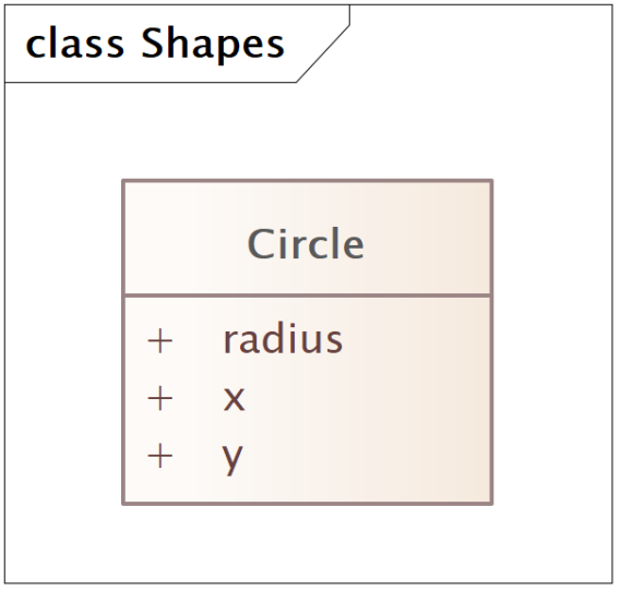
The Circle Class
If 100 circles were to be instantiated in the diagram the system would create 100 separate instances of circle, each containing an X and Y coordinate and a radius, but all are independent of each other. A change in one circle’s radius will not affect any other.
Obviously, a diagram containing only circles is not particularly useful so it would be useful if it could contain rectangles, triangles, squares, lines, and so on. This will require the class structure to become more complex.
Footnotes
5 W3C Recommendation, “Extensible Markup Language” Version 1.0, October 2000, available at https://www.w3.org/TR/REC-xml.
Inheritance
Inheritance (also known as Generalization) defines a class as being a sub-class of another class. As a sub-class, it inherits all the attributes of its parent, but can also contain its own attributes.
Classes can be abstract or concrete, depending on whether they are expected to be instantiated. If the class is in the class hierarchy to define an abstract class that represents a common parent for many other classes then it is considered abstract, but if it is something that may be instantiated then it is concrete.
An example of this is that circles, rectangles, triangles, squares, and so on, are all shapes. If a Shape class is added as a parent class, then a Circle, Rectangle and Triangle class can all be considered to be subclasses of Shape. In addition, a Square can be considered to be a subclass of Rectangle. Since the user will not be creating instances of Shape it is considered to be an abstract class while its children are all concrete classes as the diagram will contain circles, rectangles, triangles, circles, and so on.
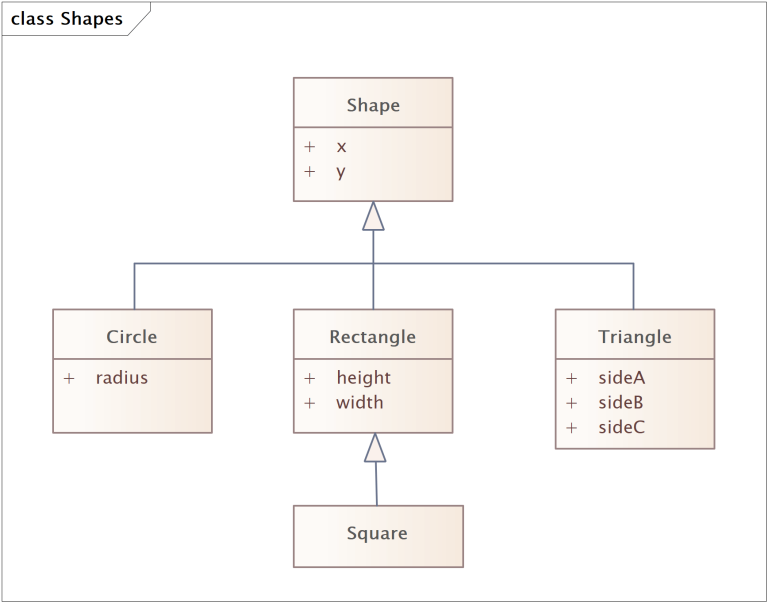
Class hierarchy for a diagram of shapes
The figure above illustrates this class hierarchy with the abstract Shape class along with its child classes Circle, Rectangle and Triangle and Square as a subclass of Rectangle. Since every shape will have a location in the diagram the X and Y coordinates are moved from Circle to its parent Shape class and so is inherited by everything that inherits from Shape. The radius attribute remains in Circle.
The Rectangle class has additional attributes added to represent the width and height of the rectangle. Square inherits these attributes (along with x and y from Shape) and the implementation would ensure that width and height would be equal for a square. In the Triangle three attributes are added to explicitly define the length of the three sides.6
So, a Square is a Rectangle and a Shape but not all Rectangles are Squares and not all Shapes are Rectangles. A system would know that any Shape will have a coordinate, but it will only expect a Circle to have a radius and a Triangle to have sideA, sideB, and sideC.
Footnotes
6 W3C Recommendation, “Extensible Markup Language” Version 1.0, October 2000, available at https://www.w3.org/TR/REC-xml.
Association
In the previous example, the only relationship between any of the classes is that of parent-child. Classes can have other relationships defined that represent linkages between classes showing a relationship other than parent-child. As an example, given that the shapes will be drawn on a diagram, it would be beneficial if each shape could have a style associated with it representing the thickness of the outline, the outline color and the internal fill color. These styles may be used by multiple shapes and have a specific name associated with them.
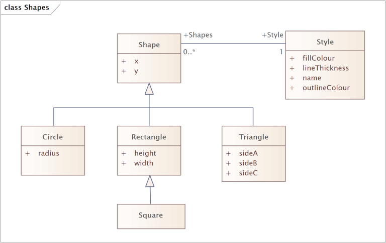
Class hierarchy of diagram shapes with a Style
In the figure above, the Style class with its three attributes for lineThickness, outlineColour and fillColour and an additional name attribute to provide a human-readable name for reference is shown with an association to Shape. The association is shown as a line between Shape and Style and the association has roles on each end. This shows that a Shape has a role Style on the Style class with cardinality of 1. This means that a Shape must have an association to an instance of Style. On the opposite side, the Style class has an association to Shape with the role name Shapes with cardinality 0..*. This means that a Style may associate with 0 or more Shapes. This means that any of the subclasses of Shape whether it is Circle, Rectangle, Triangle or Square must have a Style and they may share a common Style amongst multiple instances.
Aggregation
The Aggregation relationship defines a special kind of association between classes, indicating that one is a container class for the other. For the diagram shapes example, a Layer class is added that may contain multiple Shapes.
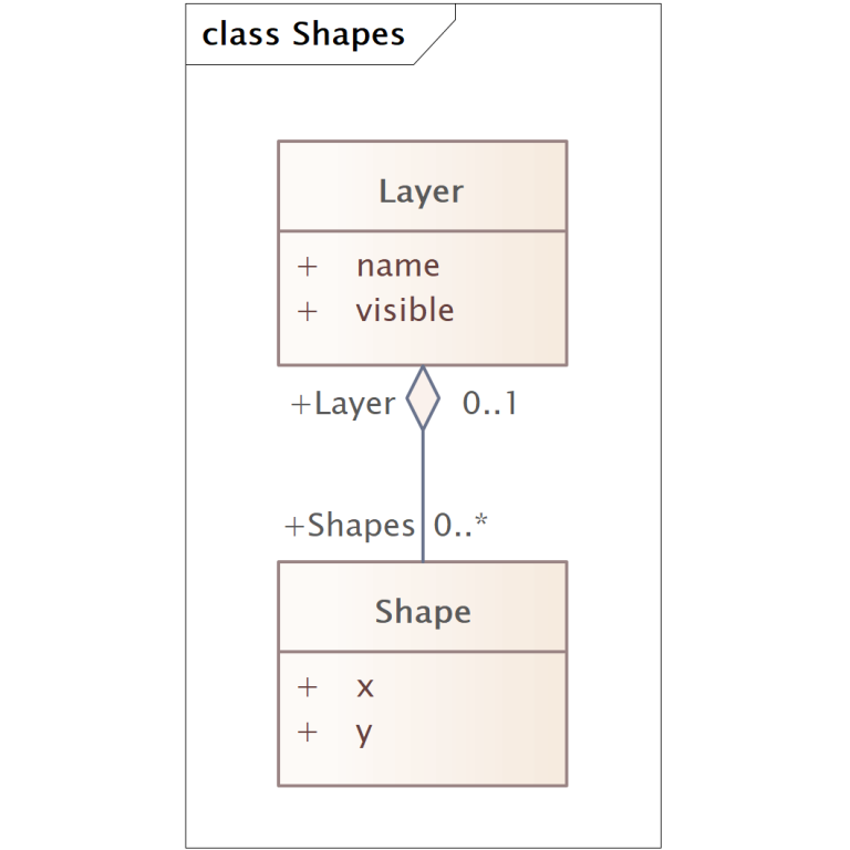
Aggregation example with Layer and Shape
In the figure above an additional class Layer is added that can be used to group together Shapes into layers that can be turned on or off within the diagram. The Layer class has attributes to provide it a name and a flag to indicate whether it visible. The relationship to Shape is an aggregation relationship, shown with a diamond on the side container side of the relationship, with role names and cardinalities used in the same way as a normal association. As such this diagram indicates that a Layer may contain 0 or more instances of Shape while a Shape will be in 0 or more Layers (it is assumed that Layers are optional). The clear diamond, however, indicates that the two are not completely inter-dependent, and that if the Layer was destroyed the Shapes would still exist.
Composition
Composition is a specialized form of aggregation where the contained object is a fundamental part of the container object. This relationship implies that if the container is destroyed then all the objects related to it via composition are similarly destroyed. In database terms this can be thought of as a cascading delete.
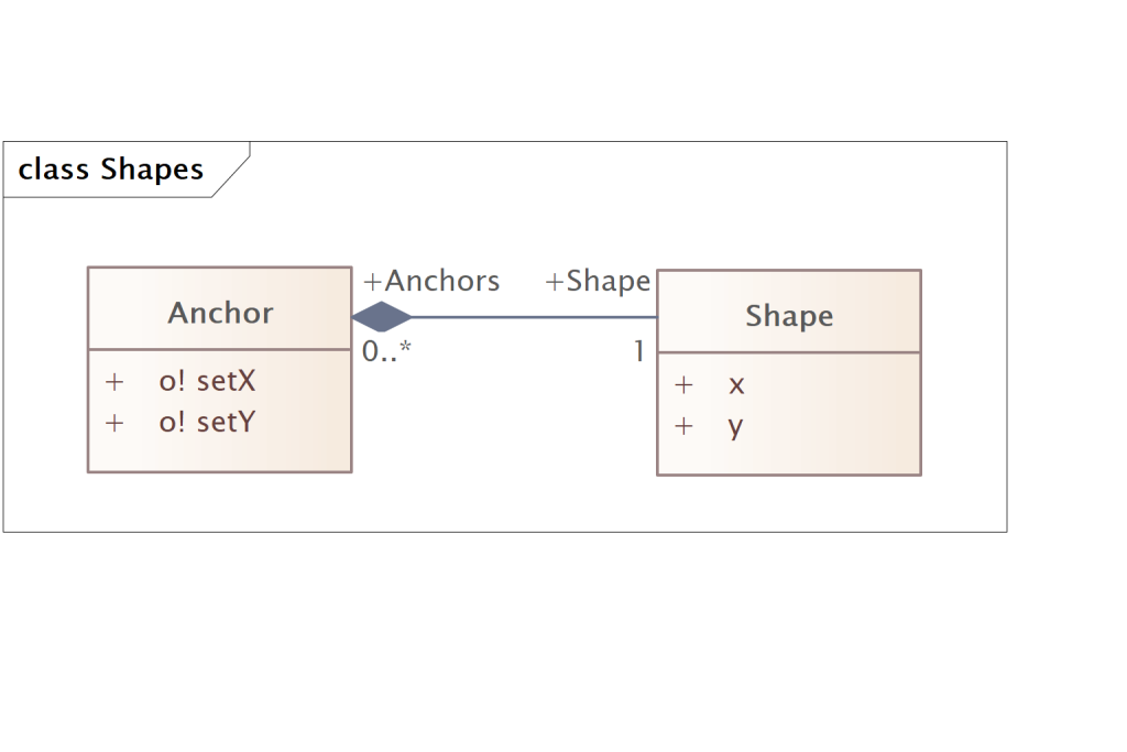
Composition example of Shape and Anchor
In the figure above, an additional class was added to represent an Anchor on a Shape that can be used show a point on the shape where a line can be anchored. The Anchor’s location is defined as an offset from its parent Shape so has an offsetX and offsetY attributes to store this location. The composition relationship to Shape has a role named Shape with cardinality 1 indicating that it must have a parent Shape. The opposite role is Anchors with 0..* showing that a Shape may have 0 or more Anchors. The filled diamond on the line shows that it is a composition relationship.
Any system that implements this design will know that if a Shape is destroyed then any Anchor instances that are contained within that particular instance will also be destroyed.
UML Summary
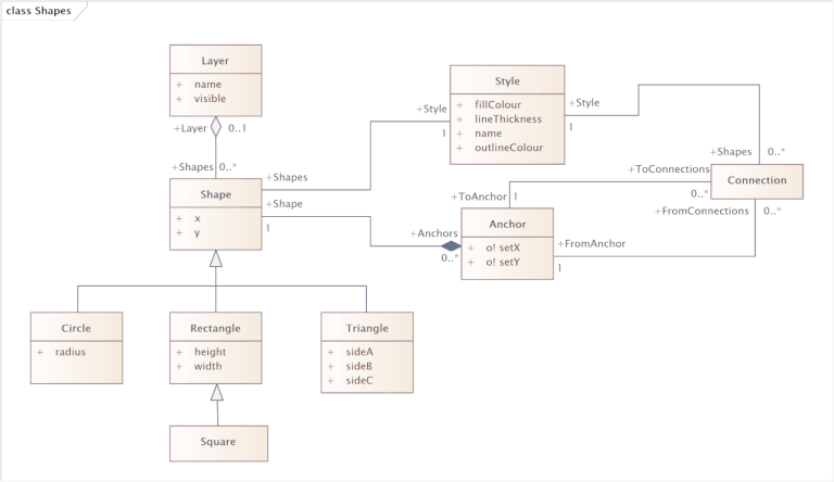
Class diagram for shapes
Combining the previous examples, a simple class diagram can be created describing how shapes are plotted on a diagram as shown in Figure 4-6.
As well as the previous examples a new class, Connection is added to represent the connection between two anchors. This class has two associations to the same class, Anchor, with different role names to differentiate between them. This allows an Anchor instance to have 0 or more Connections be associated with it as either From or To connections. A Connection must also have a FromAnchor and ToAnchor association from which it can calculate its start and end coordinates using the Anchor's offsetX and offsetY in combination with the parent Shape instance's x and y coordinates.7 The Style class is reused to allow the Connection class to have styling information to define its color and line thickness.
The previous sections should have provided some basic understanding of what a class hierarchy is and how to interpret a class diagram.
Footnotes
7 W3C Recommendation, “Extensible Markup Language” Version 1.0, October 2000, available at https://www.w3.org/TR/REC-xml.
XML Facilitates CIM-Based Data Exchange
XML Syntax
XML, the eXtensible Markup Language, is a “universal format for structured documents and data”8 which is quickly becoming the standard for storing machine-readable data in a structured, extensible format that is accessible over the Internet. XML is a meta-language9 that facilitates the design of markup language to describe the structure of the data.
XML is a subset of SGML, the Standard Generalized Markup Language10 designed for both on and offline storage and transfer of data. The data is encoded as plain text, thus allowing it to be both human and machine-readable and the use of standard encoding schemes makes it platform independent. For a detailed understanding of XML syntax the reader should refer to the XML standard documentation however, for the purposes of interpreting and understanding data serialized11 in XML, this document will try to explain the basic concepts.
XML uses tags to denote the elements within the document. Each element is either expressed as an open and close tag containing data of the form:
<tag>...Contained Data...</tag>
Or with as a single empty entry closed with a slash at the very end: <tag/>
An entry may also contain its own attributes, which are expressed in the form:
<tag attributeOne=”something” attributeTwo=”somethingElse”/> or
<tag attributeOne=”something” attributeTwo=”somethingElse”>...</tag>
When an element has a start and end tag, any elements contained within these two tags are classed as “children” of the parent element.
Simple XML Example
As an example, a simple XML tag-syntax to store a book will be created. The contents and properties of the book can then be expressed as XML, using self-descriptive tags of the form:
<book title=”Introduction to XML” author=”Alan McMorran”>
    <revision number=”2”>
    <year>2006</year>
    <month>January</month>
    <day>1</day>
  </revision>
  <chapter title=”Preface”>
    <paragraph>Welcome to <italic>this</italic> book…</paragraph>
    <paragraph>…</paragraph>
    …
    <paragraph>…and we shall continue</paragraph>
  </chapter>
  <chapter title=”Introduction”>
    <paragraph>To understand the uses…</paragraph>
    …
  </chapter>
</book>
Here the book element contains its own attribute to describe the title and author, with a child element to describe the revision of the book, plus several chapter elements. The chapters in turn contain elements for each paragraph, which themselves contain mixed data of other elements and text. Although to anybody with knowledge of the English language, the names of these tags make their semantics clear, the tag syntax and semantics must still be clearly defined if the data is to be interpreted correctly by an application.
XML Schema
While XML itself has no set tag-syntax or semantics, schemas can be defined for expressing almost any kind of data using XML notation. An application interpreting XML data must be given this knowledge of the syntax and semantics used; otherwise it will have trouble interpreting it. This requires the tag-syntax and semantics of the XML to be expressed as a schema, which provides constraints on the structure and contents of an XML document. The most common formats for describing these schemas are in Document Type Definition (DTD)12 format or the newer XML Schema Definition (XSD).13 The XSD defines:
- The elements and attributes that can appear in a document
- Which elements are child elements
- The number of allowed child elements for each element type
- Whether an element can include text (that is, is an empty element or within an open and close tags)
- The data types for elements and attributes
- Whether their values are fixed
- If there are any default values
Using the previous book example, a simple XSD can be created to describe the elements within the document and the restrictions placed on them. This example schema is shown, along with additional comments, in the figure below.
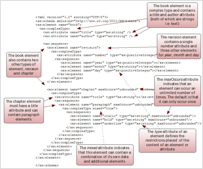
Annotated simple XML Schema Example describing the data within a book
The same schema can be viewed in different tools and formats. The figure below shows the same schema visualized in the format popular with applications such as Altova XMLSpy.14
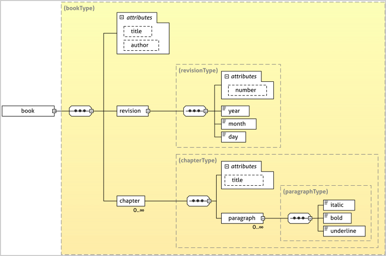
XMLSpy Style XML Schema View
The other notable feature of this document is the introduction of namespaces. In the example above, every element is prefixed by xs:.The document’s root node contains an xmlns:xs=”http://www.w3.org/2001/XMLSchema” attribute which indicates that every element prefixed with xs is an XML element that is part of the namespace identified by the Unique Resource Identifier (URI) http://www.w3.org/2001/XMLSchema.15 An XML document can contain elements from multiple namespaces simultaneously, each of which denote a separate XSD with its own set of restrictions. For the previous example, the root node could become:
<xs:schema xmlns:xs="http://www.w3.org/2001/XMLSchema"
xmlns:ab="http://www.example.com/2011/AB-Schema"
xmlns:yz="http://www.example.com/2010/YZ-Schema">
Indicating that the XML document may contain elements from the http://www.example.com/2011/AB-Schema namespace, identified by an ab prefix, along with elements from http://www.example.com/2010/YZ-Schema namespace, identified by a yz prefix in addition to the original http://www.w3.org/2001/XMLSchema namespace.
This means that an XSD itself has an XSD that describes the elements that are allowed within the schema. The use of namespace makes the format very extensible, enabling the mixing of data from different definitions in a single document without breaking importers that need only process the data defined by a schema it recognizes.
The XSD can provide an interface contract that allows two parties to agree on a well-defined structure for data that is to be exchanged and systems can then validate imported or exported data against the XSD.
Footnotes
8 W3C Recommendation, “Extensible Markup Language” Version 1.0, October 2000, available at https://www.w3.org/TR/REC-xml.
9 A meta-language is a language used to describe a language (whether it be another language or itself).
10 Information processing - Text and office systems - Standard Generalized Markup Language (SGML), ISO 8879.
11 Serialization is the process of converting a data structure into a format that can be stored and then retrieved later whether it is in a memory buffer, file or transmitted across a network. A file format is an example of a serialization format, where data is written to a file in a set format that can then be read again later, recreating an identical in-memory data structure.
12 W3C Recommendation, “Extensible Markup Language: Prolog and Document Type Declaration” Version 1.0, October 200, available at https://www.w3.org/TR/REC-xml/#sec-prolog-dtd.
13 W3C Recommendation, “XML Schema Part 0: Primer Second Edition”, October 2004, available at https://www.w3.org/TR/xmlschema-0.
14 XMLSpy is a commercial XML Editor from Altova, https://www.altova.com/xmlspy-xml-editor.
15 The W3C is the World Wide Web Consortium, the governing body for web standards. Their domain is w3.org and as such W3C standards such as XML Schema and RDF use this domain as part of their unique resource identifier.
Resource Description Framework
The Resource Description Framework (RDF)16 is an XML schema used to provide a framework for data in an XML format by allowing relationships to be defined between XML nodes. As with XML the reader is encouraged to explore the RDF specification for a detailed explanation of the format. This document will try to explain RDF in the context of how it is used with the CIM.
RDF Syntax
With a basic XML document there is no way to denote a link between two elements that are not a parent or a child. For instance, consider a library system containing entries for multiple books with information on their shelf position in the form:
<library name="Engineering Library">
  <book title="Power Systems, 1900-1950" author="J.R. McDonald">
       <position section="A" shelf="2"/>
    </book>
    <book title="A Brief History of Time" author="Stephen Hawking">
       <position section="E" shelf="4"/>
    </book>
    <book title="Power Systems, 1950-2000" author="J.R. McDonald">
       <position section="A" shelf="2"/>
    </book>
</library>
Each book element is contained within the library as an independent entry, but should the user wish to add a link between the Power Systems, 1900-1950 and Power Systems, 1950-2000 books to indicate that reader may wish to read the former book before the latter, there is no standard way to do this using the basic XML constructs.17
Within an RDF document each element can be assigned a unique ID attribute under the RDF namespace http://www.w3.org/1999/02/22-rdf-syntax-ns# (which generally uses the rdf prefix). Adding a resource attribute to an element allows references to be made between elements by having its value refer to another element’s ID.
Simple RDF Example
For the library example above, assigning an ID under the RDF namespace to each book allows the addition of sequel and sequelTo elements. These elements contain only a single resource attribute that point to another element within the document by referencing their ID. The containment of books within the library element is replaced with a reference between each book and the library it is in. To distinguish between the library elements and attributes, themselves governed by an XML Schema, and the RDF elements and attributes, an additional namespace http://www.example.com/libraries/2011/library-schema# is added with the prefix lib. An RDF root element is also added with xmlns attributes to denote the namespaces and prefixes. The new Library RDF XML representation is shown below:
<rdf:RDF xmlns:rdf="http://www.w3.org/1999/02/22-rdf-syntax-ns#"
xmlns:lib="http://www.example.com/libraries/2011/library-schema#">
    <lib:library rdf:ID="_lib0001">
       <lib:library.name>Engineering Library </lib:library.name>
    </lib:library>
    <lib:book rdf:ID="_entry0001">
     <lib:book.title>Power Systems, 1900-1950 </lib:book.title>
     <lib:book.author>J.R. McDonald </lib:book.author>
       <lib:book.position>
         <lib:position>
            <lib:position.section>A </lib:position.section>
            <lib:postion.shelf>2 </lib:position.shelf>
         <lib:position>
     </lib:book.position>
       <lib:book.sequel rdf:resource="#_entry0003"/>
       <lib:book.library rdf:resource="_lib0001"/>
    </lib:book>
    <lib:book rdf:ID="_entry0002">
       <lib:book.title>A Brief History of Time </lib:book.title>
       <lib:book.author>Stephen Hawking </lib:book.author>
       <lib:book.position>
           <lib:position>
              <lib:position.section>E </lib:position.section>
              <lib:postion.shelf>4 </lib:position.shelf>
           <lib:position>
       </lib:book.position>
       <lib:book.library rdf:resource="_lib0001"/>
    </lib:book>
    <lib:book rdf:ID="_entry0003">
       <lib:book.title>Power Systems, 1950-2000 </lib:book.title>
       <lib:book.author>J.R. McDonald </lib:book.author>
       <lib:book.position>
           <lib:position>
              <lib:position.section>A </lib:position.section>
              <lib:postion.shelf>2 </lib:position.shelf>
           </lib:position>
       </lib:book.position>
       <lib:book.sequelTo rdf:resource="#_entry0001"/>
       <lib:book.library rdf:resource="_lib0001"/>
    </lib:book>
</rdf:RDF>
As shown, the RDF provides a means of showing relationships between elements without the standard parent-child relationship previously shown with the XML example.
RDF schema contains additional elements that go beyond the simple ID and resource attribute but in the context of the CIM the concern is with the portions of RDF used within the IEC standards for serializing CIM as RDF XML so as to allow the reader to interpret and understand CIM RDF XML.
RDF Schema
While RDF provides a means of expressing simple statements about the relationship between resources, it does not define the vocabulary of these statements. The RDF Vocabulary Description Language, known as RDF Schema (RDFS)18 provides the user with a means of describing specific kinds of resources or classes. RDFS does not provide a vocabulary for a specific application's classes like lib:book.sequel or lib:book.sequelTo, or properties like lib:book.title and lib:book.author. Instead, RDFS allows the user to describe these classes and properties themselves and indicate when they should be used together. For example, they may state that the property lib:book.title will be used in describing a lib:book, or that lib:book.sequel is an element of lib:book and should indicate a reference to another lib:book entry.
In essence, RDFS provides a type system for RDF. The RDF Schema type system is similar to that of object-oriented programming languages such as Java, .NET and C++. Amongst other things, RDF Schema allows resources to be defined as instances of one or more classes and for these classes to be organized in a hierarchy.
For the previous example, the RDF Schema would, amongst others, contain entries to describe the library and book classes and the properties library, sequel and sequelTo in book.
<rdfs:Class rdf:ID="library>
  	  <rdfs:label xml:lang="en">library</rdfs:label>
  	  <rdfs:comment>The library catalogue</rdfs:comment>
</rdfs:Class>
<rdfs:Class rdf:ID="_book>
  	  <rdfs:label xml:lang="en">book</rdfs:label>
	    <rdfs:comment>A book contained within a library</rdfs:comment>
</rdfs:Class>
<rdf:Property rdf:ID="_book.library">
  	  <rdfs:label xml:lang="en">library</rdfs:label>
  	  <rdfs:comment>The library the book is in</rdfs:comment>
  	  <rdfs:domain rdf:resource="#_book"/>
  	  <rdfs:range rdf:resource="#_library"/>
</rdf:Property>
<rdf:Property rdf:ID="_sequel">
  	  <rdfs:label xml:lang="en">sequel</rdfs:label>
  	  <rdfs:comment>Indicates that the book has a sequel that is also within the library</rdfs:comment>
  	  <rdfs:domain rdf:resource="#_book"/>
  	  <rdfs:range rdf:resource="#_book"/>
</rdf:Property>
<rdf:Property rdf:ID="_sequelTo">
  	  <rdfs:label xml:lang="en">sequelTo</rdfs:label>
  	  <rdfs:comment>Indicates that the book is the sequel to another book also within the     library</rdfs:comment>
  	  <rdfs:domain rdf:resource="#_book"/>
  	  <rdfs:range rdf:resource="#_book"/>
</rdf:Property>
Here, the classes of book and library are defined, then the three properties library, sequel and sequelTo are defined. Each of these properties has their domain (the class the property is within) referencing the book class, and for the library property the range (the class of element the property refers to) is the library class while the sequel and sequelTo properties have a range of book.
Should the library schema be extended so that instead of just having a book element, fictional novels could be differentiated with a separate novel element that, when modeled in UML, would be a simple sub-class of the existing book class. This can be represented in RDF Schema as:
<rdfs:Class rdf:ID="_novel">
  	  <rdfs:label xml:lang="en">novel</rdfs:label>
  	  <rdfs:comment>A fictional book</rdfs:comment>
  	  <rdfs:subClassOf rdf:resource="#_book"/>
</rdfs:Class>
The RDF, combined with RDF Schema, provides a mechanism for expressing a basic class hierarchy as an XML schema by specifying the basic relationship between classes and properties. This then allows a set of objects to be expressed as XML using a defined schema that retain their relationships and class hierarchy.
RDF and XML provide a means to express UML, in a syntactic representation that facilitates the use of model to define interfaces, data definition language (DDL) for database design, or for programming business logic.
Footnotes
16 W3C Recommendation, “Resource Description Framework”, February 1999, available at https://www.w3.org/TR/REC-rdf-syntax.
17 There are a number of different ways this could be done, using customized attributes, XPath references etc. but XML Schema on its own does not define a standard for doing so.
18 W3C Recommendation, “RDF Vocabulary Description Language 1.0: RDF Schema”, Version 1.0, February 2004, available at https://www.w3.org/TR/rdf-schema.
Case Study
Jeff Kimble, as the manager of the integration effort at Electric Innovation Utility, has already been exposed to the “acronym soup” of syntactic representation. The integration effort EIU uses an enterprise service bus to facilitate integration and service reuse. The utility already has many services that use Java Messaging Services (JMS), web services, as well as more traditional file and database adapters that are used to connect applications. Jeff recognizes that the XML and XSDs are some of the same ways that the vendors uses to expose interfaces and so as EIU can take advantage of the CIM they will be able to leverage their existing investment in services infrastructure.
Questions to Ponder:
- Does your organization have one or more enterprise service buses?
- Does your organization have a governance model for integration?
- Does your organization promote the reuse of system interfaces?
An XML Schema Definition (XSD), can define:
A
The data types for elements and attributes
B
Whether their values are fixed
C
If there are any default values
D
All of the above
D. All of the above
If a class is a sub-class of another class it means that:
A
The class inherits all the attributes of its parent, but can also contain its own attributes.
B
The class inherits all the attributes of its parent, but cannot contain its own attributes.
C
The class has certain attributes that complement the class it is associated with.
D
The class is an aggregation of other classes.
A. The class inherits all the attributes of its parent, but can also contain its own attributes.
In the examples used in this chapter, Shape was what type of class:
A
Abstract
B
Sub-class
C
Generalization
D
Concrete
A. Abstract
One advantage of RDF over XSD is that:
A
The elements have a start and an end tag.
B
RDF can define relationships between classes and properties beyond parent-child.
C
RDF provides a means to express UML syntactically.
D
For the same set of classes and attributes, RDF is much less verbose.
B. RDF can define relationships between classes and properties beyond parent-child.
If a class is associated with another class it means that:
A
The class inherits all the attributes of its parent, but can also contain its own attributes.
B
The class inherits all the attributes of its parent, but cannot contain its own attributes.
C
The class has certain attributes that complement the class it is associated with.
D
The class is an aggregation of other classes.
C. The class has certain attributes that complement the class it is associated with.