Learning Objectives
- Understand how to map CIM into an RDF format
- Understand how difference files are used
As seen in Section 4, since the RDF and RDF Schema provide a means of mapping an object-oriented design to XML the CIM class structure can be mapped in a similar way. Existing tools can automatically generate an RDF Schema from the original CIM UML model.
This will directly map the CIM UML into RDF Schema and thus allow the CIM data objects to be mapped, one-to-one, into RDF instance data. RDF Schema supports a full class hierarchy and the subset used for CIM RDF XML30 provides a logical serialization of CIM data into a standard XML format.
Using the previous example of the Transformer class hierarchy shown in Figure 5-13, the resulting RDF Schema takes the form.
<rdfs:Class rdf:ID="PowerSystemResource">
  <rdfs:label xml:lang="en">PowerSystemResource</rdfs:label>
  	  <rdfs:subClassOf rdf:resource="#IdentifiedObject"/>
</rdfs:Class>
<rdfs:Class rdf:ID="Equipment">
  	  <rdfs:label xml:lang="en">Equipment</rdfs:label>
	    <rdfs:subClassOf rdf:resource="#PowerSystemResource"/>
</rdfs:Class>

<rdfs:Class rdf:ID="ConductingEquipment">
  	  <rdfs:label xml:lang="en">ConductingEquipment</rdfs:label>
  	  <rdfs:subClassOf rdf:resource="#Equipment"/>
</rdfs:Class>
<rdfs:Class rdf:ID="PowerTransformer">
  	  <rdfs:label xml:lang="en">PowerTransformer</rdfs:label>
  	  <rdfs:subClassOf rdf:resource="#Equipment"/>
</rdfs:Class>
<rdfs:Class rdf:ID="TransformerWinding">
  	  <rdfs:label xml:lang="en">TransformerWinding</rdfs:label>
  	  <rdfs:subClassOf rdf:resource="#ConductingEquipment"/>
</rdfs:Class>
<rdfs:Class rdf:ID="TapChanger">
  	  <rdfs:label xml:lang="en">TapChanger</rdfs:label>
  	  <rdfs:subClassOf rdf:resource="#PowerSystemResource"/></rdfs:Class>
</rdfs:Class>
<rdf:Property rdf:ID="TransformerWinding.PowerTransformer">
  	  <rdfs:label xml:lang="en">PowerTransformer</rdfs:label>
  	  <rdfs:domain rdf:resource="#TransformerWinding"/>
  	  <rdfs:range rdf:resource="#PowerTransformer"/>
</rdf:Property>
<rdf:Property rdf:ID="TapChanger.TransformerWinding">
  	  <rdfs:label xml:lang="en">TransformerWinding</rdfs:label>
  	  <rdfs:domain rdf:resource="#TapChanger"/>
  	  <rdfs:range rdf:resource="#TransformerWinding"/>
</rdf:Property>
Each CIM Class has a corresponding rdfs:Class entry, while the two aggregation relationships are expressed as RDF Property elements with the appropriate domains and ranges. The entire CIM Class structure can be expressed in this manner, and then this RDF Schema can be used to express a CIM power system model as RDF XML.
Footnotes
30 IEC 61970-552 uses only a subset of the full W3C RDF standard. This allows a direct mapping between the CIM UML and RDF Schema without introducing additional choice or complexity. This simplifies parsing of CIM RDF XML data while maintaining compatibility with the standard. The result is that any RDF XML parser should be able to read CIM RDF XML but a parser written specifically for CIM RDF XML may not be able to cope with other RDF XML files that utilize the full specification.
CIM RDF Serialization Examples
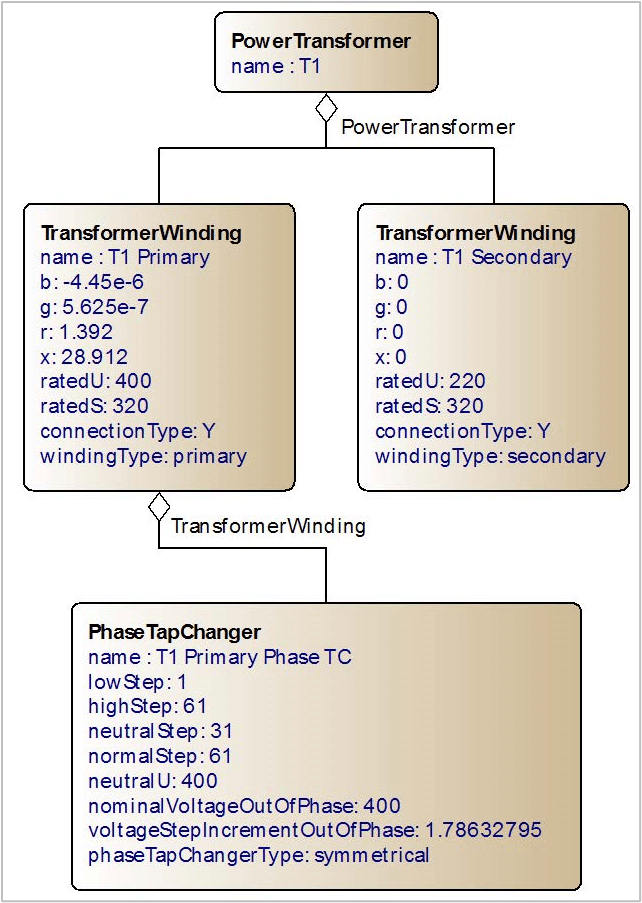
This class structure then defines how the instance data itself will look in an RDF format. As an example, the simple Transformer example from Figure 5-14 will be extended to include attributes for each object. This produces four objects with their own internal data as shown in Figure 7-1 below.
Each of these objects can then be expressed as an XML node using the CIM RDF Schema given the namespace http://iec.ch/TC57/2009/CIM-schema-cim14# and prefix cim: (the prefix itself can be set to any arbitrary alphanumeric string, but generally it is set as cim for CIM RDF XML exchanges). The resulting CIM RDF XML sample is shown below:
<rdf:RDF xmlns:rdf="http://www.w3.org/1999/02/22-rdf-syntax-ns#"
  xmlns:cim="http://iec.ch/TC57/2009/CIM-schema-cim14#">

  <cim:PowerTransformer rdf:ID="_1b8e9e856a5711dfa90800059a3c7800">
    <cim:IdentifiedObject.name>T1</cim:IdentifiedObject.name>
  </cim:PowerTransformer>

  <cim:TransformerWinding rdf:ID="_1b8e9e876a5711dfa90800059a3c7800">
      <cim:IdentifiedObject.name>T1 Primary</cim:IdentifiedObject.name>
      <cim:TransformerWinding.b>-4.45E-06</cim:TransformerWinding.b>
      <cim:TransformerWinding.g>5.625E-07</cim:TransformerWinding.g>
      <cim:TransformerWinding.r>1.392</cim:TransformerWinding.r>
      <cim:TransformerWinding.x>28.912</cim:TransformerWinding.x>
      <cim:TransformerWinding.ratedU>400</cim:TransformerWinding.ratedU>
      <cim:TransformerWinding.ratedS>320</cim:TransformerWinding.ratedS>
      <cim:TransformerWinding.connectionType
         rdf:resource="http://iec.ch/TC57/2009/CIM-schema-cim14#WindingConnection.Y"/>
      <cim:TransformerWinding.windingType
         rdf:resource="http://iec.ch/TC57/2009/CIM-schema-cim14#WindingType.primary"/>
      <cim:TransformerWinding.PowerTransformer
         rdf:resource="#_1b8e9e856a5711dfa90800059a3c7800"/>
  </cim:TransformerWinding>

  <cim:TransformerWinding rdf:ID="_1b8e9e906a5711dfa90800059a3c7800">
      <cim:IdentifiedObject.name>T1 Secondary </cim:IdentifiedObject.name>
      <cim:TransformerWinding.b>0</cim:TransformerWinding.b>
      <cim:TransformerWinding.g>0</cim:TransformerWinding.g>
      <cim:TransformerWinding.r>0</cim:TransformerWinding.r>
      <cim:TransformerWinding.x>0</cim:TransformerWinding.x>
      <cim:TransformerWinding.ratedU>220</cim:TransformerWinding.ratedU>
      <cim:TransformerWinding.ratedS>320</cim:TransformerWinding.ratedS>
      <cim:TransformerWinding.connectionType
         rdf:resource="http://iec.ch/TC57/2009/CIM-schema-cim14#WindingConnection.Y"/>
      <cim:TransformerWinding.windingType
        rdf:resource="http://iec.ch/TC57/2009/CIM-schema-cim14#WindingType.secondary"/>
      <cim:TransformerWinding.PowerTransformer
      rdf:resource="#_1b8e9e856a5711dfa90800059a3c7800"/>
  </cim:TransformerWinding>

  <cim:PhaseTapChanger rdf:ID="_1b8e9e8e6a5711dfa90800059a3c7800">
      <cim:IdentifiedObject.name>T1 Primary Phase TC</cim:IdentifiedObject.name>
      <cim:TapChanger.lowStep>1</cim:TapChanger.lowStep>
      <cim:TapChanger.highStep>61</cim:TapChanger.highStep>
      <cim:TapChanger.neutralStep>31</cim:TapChanger.neutralStep>
      <cim:TapChanger.normalStep>61</cim:TapChanger.normalStep>
      <cim:TapChanger.neutralU>400</cim:TapChanger.neutralU>
      <cim:PhaseTapChanger.nominalVoltageOutOfPhase>400
       </cim:PhaseTapChanger.nominalVoltageOutOfPhase>
      <cim:PhaseTapChanger.voltageStepIncrementOutOfPhase>1.78632795
       </cim:PhaseTapChanger.voltageStepIncrementOutOfPhase>
      <cim:PhaseTapChanger.phaseTapChangerType
         rdf:resource="http://iec.ch/TC57/2009/CIM-schema-
           cim14#PhaseTapChangerKind.symmetrical"/>
      <cim:PhaseTapChanger.TransformerWinding
       rdf:resource="#_1b8e9e876a5711dfa90800059a3c7800"/>
  </cim:PhaseTapChanger>

</rdf:RDF>
The TransformerWinding.connectionType, TransformerWinding.windingType and PhaseTapChanger.phaseTapChangerType elements do not refer to other nodes within the document; instead their values are of an enumerated type. Enumerated types consist of a fixed set of legal values (that is, for a variable of type Days, the enumerated type would be: Sunday, Monday, Tuesday, Wednesday, Thursday, Friday, Saturday and any variable of this type must have one of these values).
Within the CIM there are certain class attributes that are also enumerated types and do not contain a node value but instead refer to an enumerated type within its RDF Schema. This combination of the CIM, XML, RDF and RDF Schema allows an entire CIM power system model to be expressed in a standard, cross-platform plain-text format that is both human and machine readable and extensible.
Object/Node Identification
The CIM contains an attribute, mRID on the IdentifiedObject class that is the root for any class that is expected to be persisted beyond a single exchange.31 In RDF every node has to have its own unique ID in the form of the rdf:ID (that is, an attribute ID under the RDF namespace, commonly denoted with the lowercase prefix rdf).
The convention with CIM RDF XML is that the rdf:ID will be the same as an object’s mRID and thus the mRID is omitted. However, every node within a CIM RDF XML file requires an rdf:ID, even those that do not inherit from IdentifiedObject. All RDF nodes will therefore have an rdf:ID and they should be persisted within an exchange between systems, that is, if A transmits CIM RDF XML data to B and B makes some updates or modifications, then the CIM RDF XML sent back from B to A should use the same rdf:IDs as the original exchanges.
The recommendation from the IEC working group is that these rdf:IDs should be Universally Unique Identifiers32 (UUIDs) also known as Globally Unique Identifiers (GUID) when referring to Microsoft’s implementation. The RDF standard specified that an ID may not start with a number, only an underscore or character, so it is common to find all rdf:IDs in CIM RDF XML data prefixed with the underscore character.
Identifier Scope
Technically the true unique identity of a node is the concatenation of the local rdf:ID with the base Unique Resource Identifier (URI) of the file itself. As such a node of ID 123456 within the file with base URI http://example.com/my/file has the unique identity http://example.com/my/file#_123456. CIM RDF XML exchanges, by using the mRID as the rdf:ID do not necessarily follow this convention and the local node identifier is, itself, considered to be globally unique. As such any node across multiple files identified with the same rdf:ID is considered to be referring to the same, universally unique object. This means that when exchanges take place using multiple files the cross-file references use only the rdf:ID.
Footnotes
31 This means any object that is likely to be referenced or persisted within a system. An examples of a class that does not inherit from IdentifiedObject is CurveData which represents a point on a Curve. The Curve itself inherits from IdentifiedObject and so would be referred to by other objects and may exist in isolation. The CurveData, by contrast, is part of the curve (that is, a perfect example of composition as described in the background to UML in Section 4) so it does not need its own, persistent ID as it is the curve itself that is the persistent entity.
32 See IETF RFC 4122 at https://www.ietf.org/rfc/rfc4122.txt.
Extensibility and Efficiency
RDF XML is a verbose, self-descriptive format and so offers a number of benefits and perceived drawbacks. As the example above shows, with an RDF XML format every data element has descriptive tags. This allows the format to be extensible as additional elements can be added without ‘breaking’ parsers that rely on fixed formats.
Extensibility
By using the XML namespaces, additional elements are added under different namespaces. In the example below the namespace http://example.com/extension# is used to define an additional type element for the PowerTransformer class.
<rdf:RDF xmlns:rdf="http://www.w3.org/1999/02/22-rdf-syntax-ns#"
  xmlns:cim="http://iec.ch/TC57/2009/CIM-schema-cim14#"
  xmlns:ex="http://example.com/extension#">
  <cim:PowerTransformer rdf:ID="_1b8e9e856a5711dfa90800059a3c7800">
    <cim:IdentifiedObject.name>T1</cim:IdentifiedObject.name>
    <ex:PowerTransformer.type>SuperGrid</ex:PowerTransformer.type>
  </cim:PowerTransformer>
</rdf:RDF>
For those parsers that do not recognize or understand the additional namespace the extra elements are simply ignored. Multiple additional namespaces can be used, allowing additional, extended data to be integrated with the standard CIM data within a single file.
Compression and Efficiency
The nature of XML, its verbose format where the XML tag elements often take up more space then the actual instance data itself, results in large file sizes. This is often perceived as a weakness of CIM RDF XML over more traditional, fixed-width, comma or whitespace delimited formats.
This assumes that the CIM RDF XML will be transmitted as uncompressed data, ignoring the significant reduction in file size that can be accomplished with ZIP compression, an archive file format with near-ubiquitous support on modern computing environments. The format provides a means of compressing and archiving multiple files into a single entity using the DEFLATE33 lossless data compression algorithm, itself based on LZ7734 and Huffman coding.35
Other widely-used application formats including Oracle's Java Archive format (JAR), Microsoft’s Office Open XML, Google’s compressed Keyhole Markup Language (KMZ) and ISO/IEC 26300:2006 Open Document Format (ODF) all use ZIP to compress either a single file or multiple file into a single compressed archive file. This approach maintains the underlying data hierarchies and for ODF, Office Open XML and KMZ the underlying XML files, while significantly reducing the size of the resulting file.
Using the same approach with CIM RDF XML data file sizes can be reduced by a factor of over 20, thus reducing a 3GB CIM RDF XML file to a ZCIM file of approximately 120Mb or less. The ZIP archive format compresses each individual file independently, and as such the files within the archive can be read independently without requiring the entire archive to be decompressed first. With modern languages such as .NET and Java having native support for reading and writing to ZIP archives and free libraries available for C, C++ and other common languages, applications can deal with these ZIP files and parse the individual XML files without having to ever decompress the entire file to disk.
While reading from and writing to ZIP archives does involve extra processor overhead to perform the compression and decompression, initial tests with large real-world CIM RDF XML files has found that there is no performance penalty incurred with import and export times. This can be attributed to the decrease in disk input/output required to read a smaller file and with disk input/output being significantly slower than memory access the increase in processing time for compression and decompression is offset by the decreased disk input/output required.
Footnotes
33 P. Deutch. DEFLATE Compressed Data Format Specification version 1.3 [RFC 1951], https://www.ietf.org/rfc/rfc1951.txt, May 1996.
34 Jacob Ziv and Abraham Lempel, “A Universal Algorithm for Sequential Data Compression,” IEEE Transactions on Information Theory, May 1977, Volume 23, Number 3, pp. 337–34.3
35 D.A. Huffman, “A Method for the Construction of Minimum-Redundancy Codes”, Proceedings of the I.R.E., September 1952, pp. 1098–1102.
CIM Difference Model
Another manner of reducing the volume and complexity of the CIM RDF XML exchanges is to utilize the CIM Difference Model XML format that describes the changes between two CIM RDF XML files. This allows incremental exchanges of CIM data so that the full network model does not need to be exchanged.
The Difference Model format defines four statement sets:
- Reverse Differences
- Forward Differences
- Pre-Conditions
- Post-Conditions
(In reality the Pre and Post conditions are rarely used, and interoperability tests focus on the Forward and Reverse differences). A difference model can add new objects, remove existing objects or update objects by changing, adding or removing attributes. The Reverse Differences define the removals while Forward Differences define the additions. A change (update) is defined as a pair of Forward and Reverse differences on an existing object.
The CIM DM XML format is RDF-based and uses a similar format to that of the full model CIM RDF XML described in the previous section.
Difference Model RDF XML Format
As with the full CIM RDF XML data, the Difference Model format begins with the namespace declarations under an RDF node:
<rdf:RDF xmlns:rdf="http://www.w3.org/1999/02/22-rdf-syntax-ns#"
  xmlns:cim="http://iec.ch/TC57/2009/CIM-schema-cim14#"
  xmlns:dm="http://iec.ch/2002/schema/CIM_difference_model#">
In addition to the CIM and RDF namespaces that were present in the full model, the Difference Model namespace is included. This defines the additional elements that are used to contain the forward and reverse statements:
<dm:DifferenceModel>
  <dm:reverseDifferences parseType="Statements">
       ...
    </dm:reverseDifferences>
    <dm:forwardDifferences parseType="Statements">
       ...
    </dm:forwardDifferences>
</dm:DifferenceModel>
Inside these reverseDifferences and forwardDifferences nodes are placed the data elements that are to be added, removed or updated.
Addition
To add a CIM object the data structure is identical to that of the full CIM RDF XML format. The elements are placed with the forwardDifferences node and take the format shown below:
<dm:forwardDifferences parseType="Statements">
    <cim:ACLineSegment rdf:ID="_lang0182743">
    <cim:IdentifiedObject.name>A New Line</cim:IdentifiedObject.name>
    </cim:ACLineSegment>
</dm:forwardDifferences>
In the example above a new ACLineSegment has been added. The format and structure is identical to that of an ACLineSegment in a full RDF XML file, with the rdf:ID providing the unique identifier for the object and all attributes and associations included inline.
Deletion
The deletion of an existing object uses a very similar format, albeit under the reverseDifferences rather than the forwardDifferences node. For a deletion there are two methods for defining the node to be accomplished. The first is a shorthand syntax that defines only the object’s ID and none of the object’s attributes or associations. For example, to delete the object that was added in the example above the shorthand syntax takes the form:
<dm:reverseDifferences parseType="Statements">
    <cim:ACLineSegment rdf:ID="_lang0182743"/>
</dm:reverseDifferences>
The other approach is a more verbose syntax that includes all of the object’s attributes and associations:
<dm:reverseDifferences parseType="Statements">
    <cim:ACLineSegment rdf:ID="_lang0182743">
    <cim:IdentifiedObject.name>A New Line</cim:IdentifiedObject.name>
    </cim:ACLineSegment>
</dm:reverseDifferences>
The benefit of the shorthand syntax is that when removing a large number of objects it reduces the size of the incremental file and omits additional data that is, essentially, superfluous when the object is to be deleted anyway.
However, by using the longhand syntax, a difference file can be applied in reverse by changing all forwardDifferences to reverseDifferences and vice-versa. This allows a system to undo a difference file using only the data contained within the difference file. By storing all changes as verbose, longhand syntax incremental difference model files previous systems states can be restored without requiring additional state information to be stored separately.
The longhand syntax also has the additional benefit of allowing a system to perform additional data verification by ensuring that the object’s attributes and associations match those in the difference model. If a mismatch is identified this will alert the user that their system may be out of synchronization with whatever system generated the incremental.36
Updates
To change an existing object the syntax is slightly different. In this situation the RDF Description notation is used with the rdf:about attribute replacing rdf:ID as the identifier. This is used to indicate that the node is referencing a pre-existing object within the full model, rather than being the creation of a new object.
So, to remove an attribute or an association on an existing model, a Description element is added with the syntax:
<rdf:Description rdf:about="#_pqrs34567890">
  ...
</rdf:Description>
This refers to an existing object of ID _pqrs34567890 that already exists within the system. Inside these Description tags are placed the attributes or associations that have to be added or removed on this object. For example, to remove the association from a Terminal with the ID _pqrs34567890 to a piece of ConductingEquipment with the ID _abcdef0123456789 the resulting DM XML is:
<dm:reverseDifferences parseType="Statements">
    <rdf:Description rdf:about="#_pqrs34567890">
       <cim:Terminal.ConductingEquipment rdf:resource="#_abcdef0123456789"/>
    </rdf:Description>
</dm:reverseDifferences>
The syntax inside the Description tags is identical to that of the full model RDF XML, the difference here is that we are indicating that his association is to be removed. The corresponding forwardDifferences statement is an identical format, but by being within the forwardDifferences element it is interpreted as an addition rather than a removal from the object:
<dm:forwardDifferences parseType="Statements">
    <rdf:Description rdf:about="#_pqrs34567890">
       <cim:Terminal.ConductingEquipment rdf:resource="#_lang0182743"/>
    </rdf:Description>
</dm:forwardDifferences>
The combination of a forward and reverse statement for the object therefore results in an update, changing the ConductingEquipment association in this case from _abcdef0123456789 to _lang0182743 (the ID of the ACLineSegment that was added in the first example). Combining the addition and the updates together into a single DM XML file that adds a new ACLineSegment and changes an existing Terminal to associate with this new line we get:
<rdf:RDF xmlns:rdf="http://www.w3.org/1999/02/22-rdf-syntax-ns#"
    xmlns:cim="http://iec.ch/TC57/2009/CIM-schema-cim14#"
    xmlns:dm="http://iec.ch/2002/schema/CIM_difference_model#">
    <dm:DifferenceModel>
       <dm:reverseDifferences parseType="Statements">
           <rdf:Description rdf:about="#_pqrs34567890">
              <cim:Terminal.ConductingEquipment rdf:resource="#_abcdef0123456789"/>
           </rdf:Description>
       </dm:reverseDifferences>
       <dm:forwardDifferences parseType="Statements">
           <cim:ACLineSegment rdf:ID="_lang0182743">
              <cim:IdentifiedObject.name>A New Line </cim:IdentifiedObject.name>
           </cim:ACLineSegment>
           <rdf:Description rdf:about="#_pqrs34567890">
              <cim:Terminal.ConductingEquipment rdf:resource="#_lang0182743"/>
           </rdf:Description>
       </dm:forwardDifferences>
  </dm:DifferenceModel>
</rdf:RDF>
Footnotes
36 This is not necessarily an unexpected situation. There are several scenarios where a difference file may be applied to a base model that doesn’t exactly match that of the sending system (for example, where a difference file represents a potential network extension, and the user wants to apply it to a different planning model than the one it was created against). In this situation the user (or system) may choose to apply the differences even where there is an identified source/target mismatch.
RDF Headers
The CIM RDF XML samples above contain no meta-data to denote versioning; the type of dataset it is; any profiles to which is conforms; any dependencies between datasets; or information about the creation date and author. To address this a standard CIM Header format has been created that will be inserted at the beginning of a CIM RDF XML file to contain this meta-data. As well as embedding the information required for the actual exchange, these headers provide useful data for importers that are to deal with the network model files.
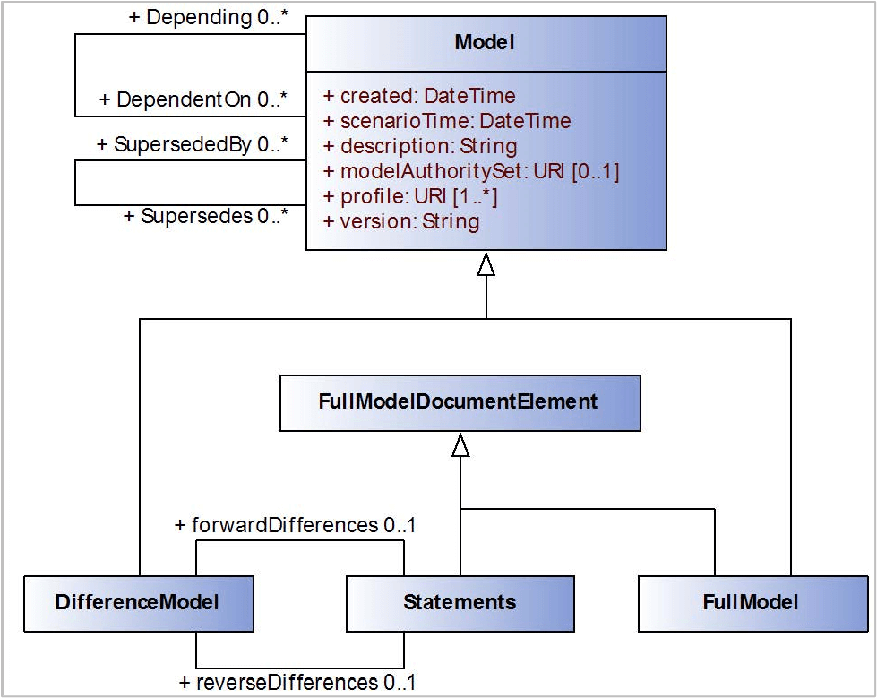
Figure 7-2 shows the UML for the CIM Header. While on first inspection the class diagram may appear complex, in reality the classes FullModel and DifferenceModel are the two concrete classes that are instantiated (sharing all the attributes and associations from the common parent class, Model). The additional classes are used so as to allow the header structure to be harmonized with that of the Difference Model format described in the previous section.
- The
FullModelDocumentElementclass describes any of the elements that may appear in the full model document itself. It has two subtypes in the form ofStatementsandFullModel. A full CIM RDF XML file typically will contain aFullModelinstance and one set ofStatementelements. - The
Statementclass represents a series of RDF XML nodes that describe the instance data for the CIM objects (either as full nodes or therdf:Descriptionelements for a Difference Model update) - The
FullModelclass is the full model header used to provide the meta-data for a CIM RDF XML instance file - The
DifferenceModelclass represents both the Difference Model Header and its root element that was shown in the previous section as:<dm:DifferenceModel> - This element contains two sub-elements of
forwardDifferencesandreverseDifferencesthat are the statements defining the additions, removals and updates. Each of these will contain one set of statements.37 - The abstract
Modelclass has the core attributes that is inherited by allDifferenceModelandFullModel. Unlike the RDF nodes described in the full CIM RDF XML instance data exchange, the header data uses therdf:aboutsyntax to define its identity rather thanrdf:ID. This uniquely identifies the model not just the file and so reflects the state of the data. The same data may be stored in two different files with different names but the unique identity in therdf:aboutwill be the same.
The resulting instance data takes the form:
<rdf:RDF xmlns:cim="http://iec.ch/TC57/2010/CIM-schema-cim15#"    xmlns:md="http://iec.ch/TC57/61970-552/ModelDefinition/1#"    xmlns:rdf="http://www.w3.org/1999/02/22-rdf-syntax-ns#">

  <md:FullModel rdf:about="urn:uuid:2399cbd4-9a39-11e0-aa80-0800200c9a66">
    <md:Model.created>2011-06-28T10:00:00</md:Model.created>
       <md:Model.scenarioTime>2012-07-15T10:30:00</md:Model.scenarioTime>
       <md:Model.version>7</md:Model.version>
       <md:Model.DependentOn
           rdf:resource="urn:uuid:2399cbd2-9a39-11e0-aa80-0800200c9a66"/>
       <md:Model.DependentOn
           rdf:resource="urn:uuid:2399cbd1-9a39-11e0-aa80-0800200c9a66"/>
       <md:Model.description>Belgium topological node data</md:Model.description>
         <md:Model.modelingAuthoritySet>http://elia.be/Planning/ENTSOE/2
         </md:Model.modelingAuthoritySet>
       <md:Model.profile>http://iec.ch/TC57/61970-456/Topology/2</md:Model.profile>
    </md:FullModel>
The result of the CIM data then proceeds this header entry as described in the previous sections. The header has a UUID for its unique identity and is Dependent On two other models, referencing them with the rdf:about in their FullModel or DifferenceModel header entries (in this case the unique ID of these models is also a UUID). The dependencies allows and importer to ensure that all the prerequisite models exist (or can be found) prior to importing. Unresolved dependencies may indicate missing files and so the user can be appropriately informed (and may choose to proceed anyway or cancel and resolve the dependency issues).
The modelingAuthoritySet attribute defines the set to which this file belongs. In exchanges where multiple files constitute a single Modeling Authority then all the files will have the same modelingAuthoritySet ID. In the example above the attribute denotes that this file is part of a set for ELIA (the Belgian Transmission Grid Operator) in the ENTSO-E exchange. Other files for the Equipment and State Variables will have the same modelingAuthoritySet ID and so the collection of these files form ELIA’s Modeling Authority Set.
The header may also denote one or more profiles that the data conforms to. This defines a minimum set of required data elements and restrictions but also allows an importer to quickly identify which of the collection of files it has received is relevant to its own particular data requirements. For example, a state-estimator has no need for geographical or schematic diagram layout data so it can quickly identify files that are superfluous and move on, ignoring their contents.
Similarly, the versioning information can be used to identify when a model has been updated from a previous import and so requiring the application to import and process the data or is the same version as the last import and thus allowing a model to be bypassed.
Footnotes
37 The Difference Model format precedes the Header definition and as such the Header was created to be backwards compatible with the pre-existing Difference Model format.
RDF Schema Definition in CIMTool
Defining the Message Structure
CIMTool is an open-source tool that supports the definition of CIM profiles. As of 2025, it can be used to generate JSON schemas, database schemas, XML schemas, RDF schemas, PlantUML, Java classes, and more. For this example, CIMTool v2.3.0 is used with CIM18.
Once a CIMTool project has been created using the CIM18 schema, a new profile can be created that will define the subset of the CIM that will be used for this grid model data management interface.
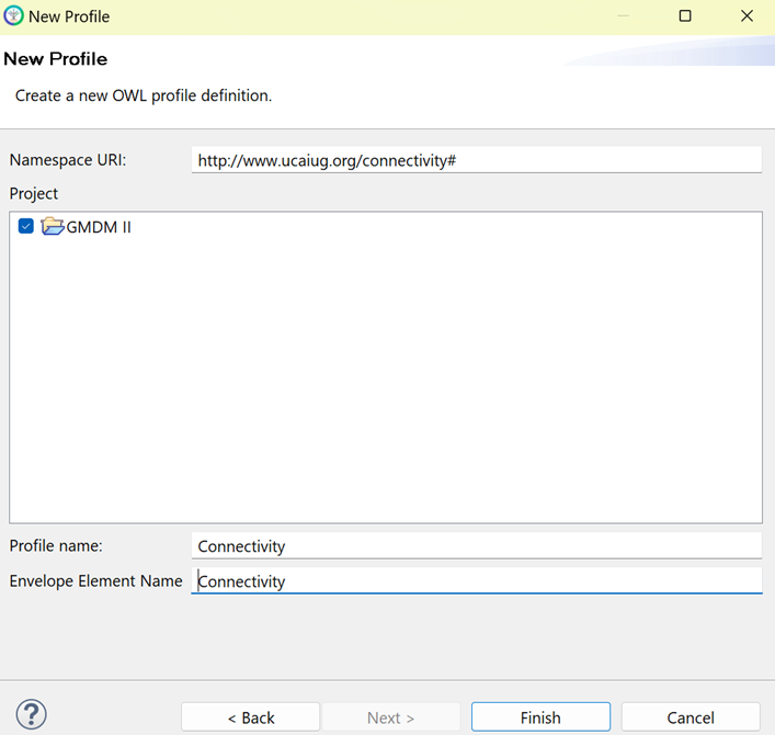
In Figure 7 3 is an example of a New Profile dialog box. Each profile has a namespace Unique Resource Identifier (URI) which in this case has been set as http://www.ucaiug.org/connectivity#. The Profile Name is used to name the profile within the workspace and the Envelope Element Name typically defines the root of the message itself. However, since this is being used to generate RDFS instead of XML schema, this will not actually be used for that purpose.
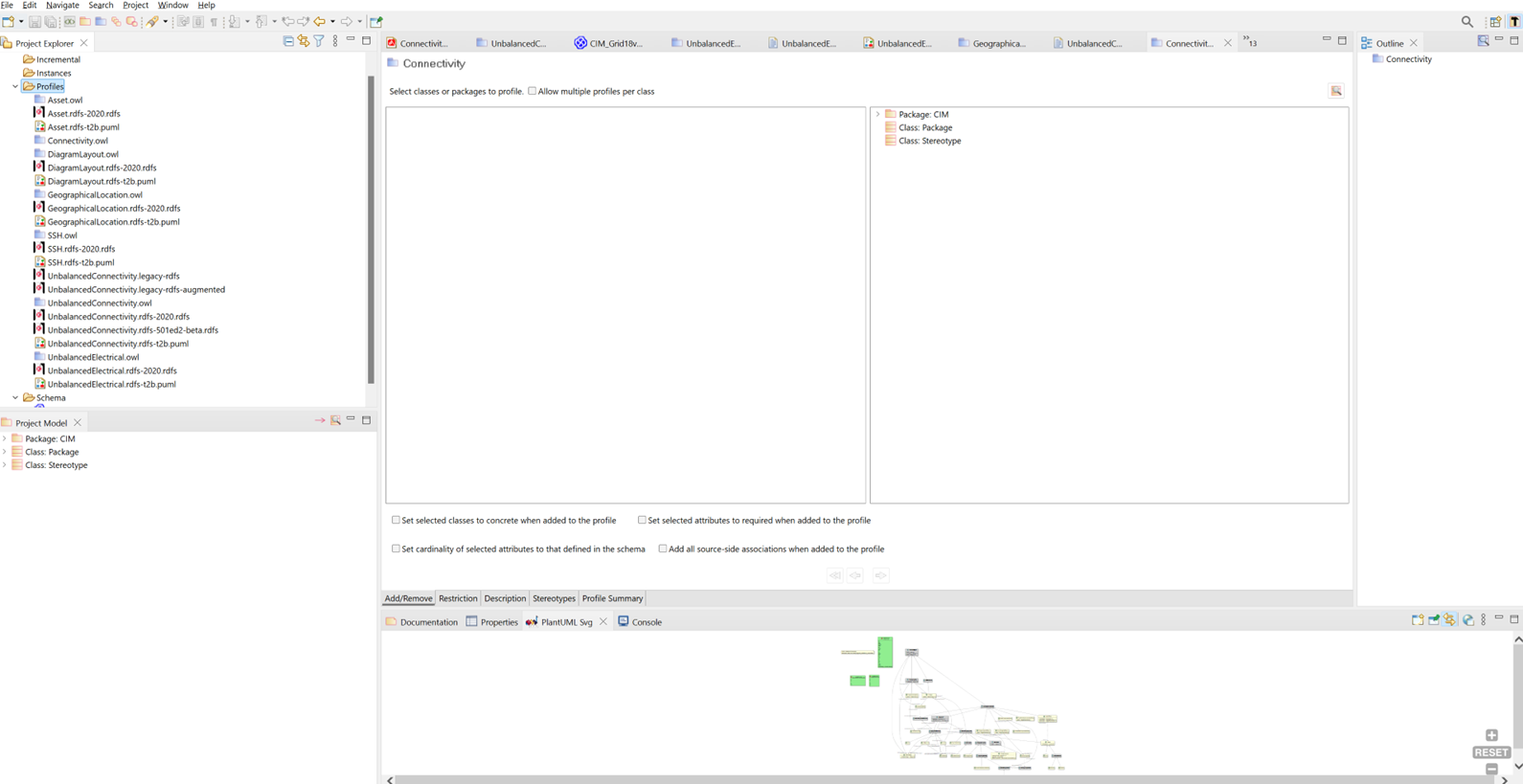
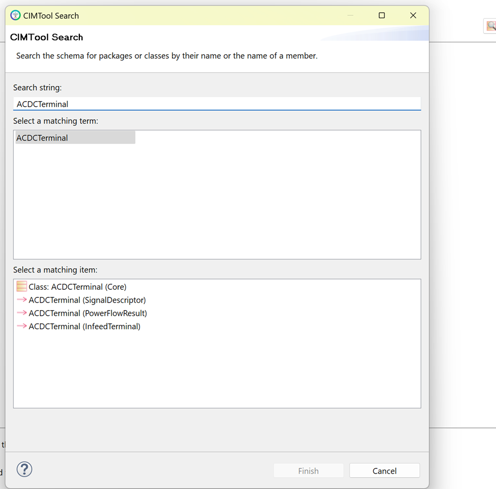
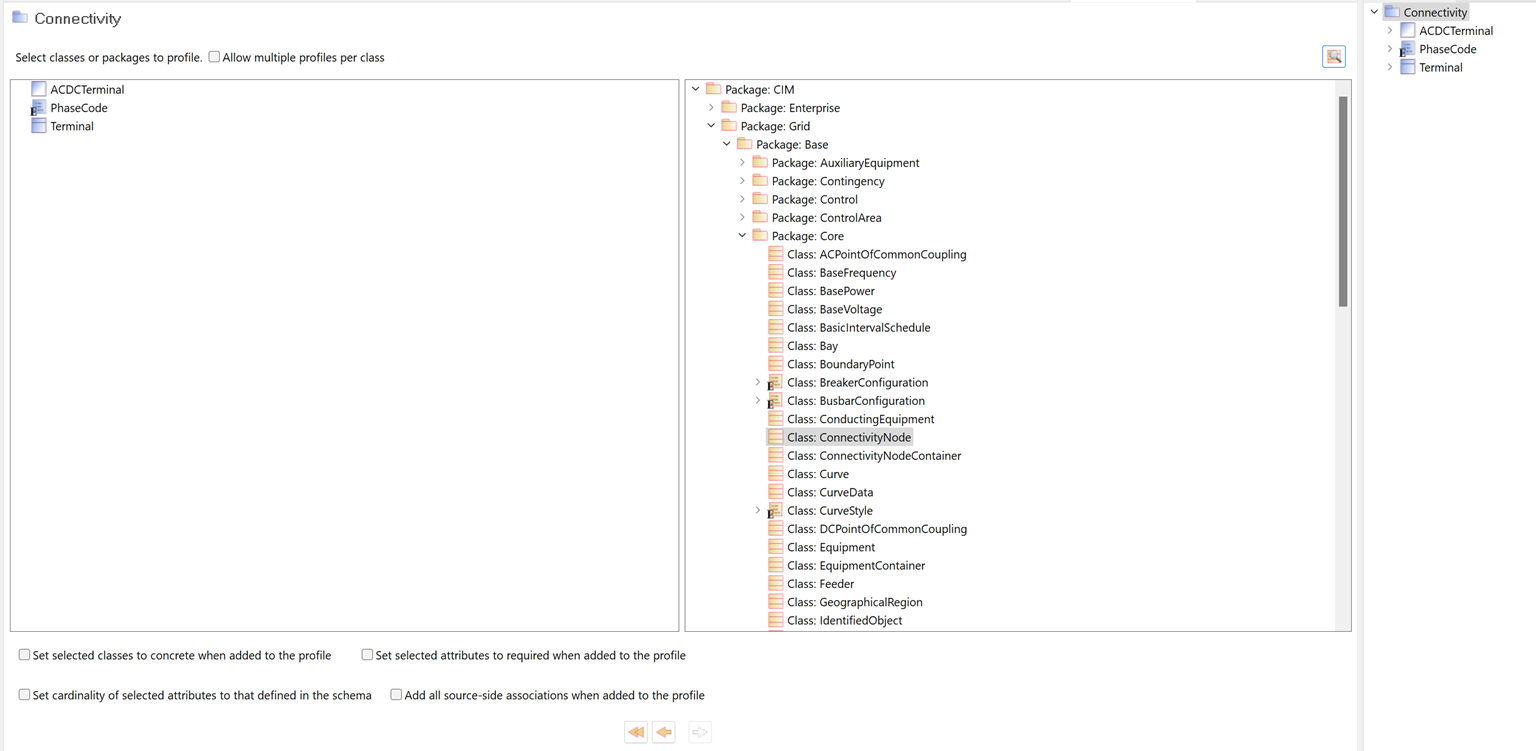
This produces an empty profile called Connectivity as shown in Figure 7 4, which can be populated with classes taken from the full CIM UML model. To do this, there are two valid approaches to take assuming the schema has been added (this can be either as an XMI file or by bringing in the .eapx file directly). Either the CIM package hierarchy can be expanded and the proper classes manually added, or the search button can be used to look up the name of the class that is to be added or removed. For this example, the latter option will be utilized.
As shown in Figure 7 5, classes can be instantly searched and then dragged over into the profile. For this example, the class ACDCTerminal was searched and then dragged into the profile using the left arrow button. This class, however, is considered an Abstract class; that is, it is not to be directly referenced in RDF messages but is brought into the profile anyway so that other classes that inherit from it can be modeled. Because this class will only inherit from IdentifiedObject and the profile has no need of any other attributes, there is nothing else to be done with this class. So next, let's bring in the Terminal class that will be a Concrete class and will inherit from ACDCTerminal.
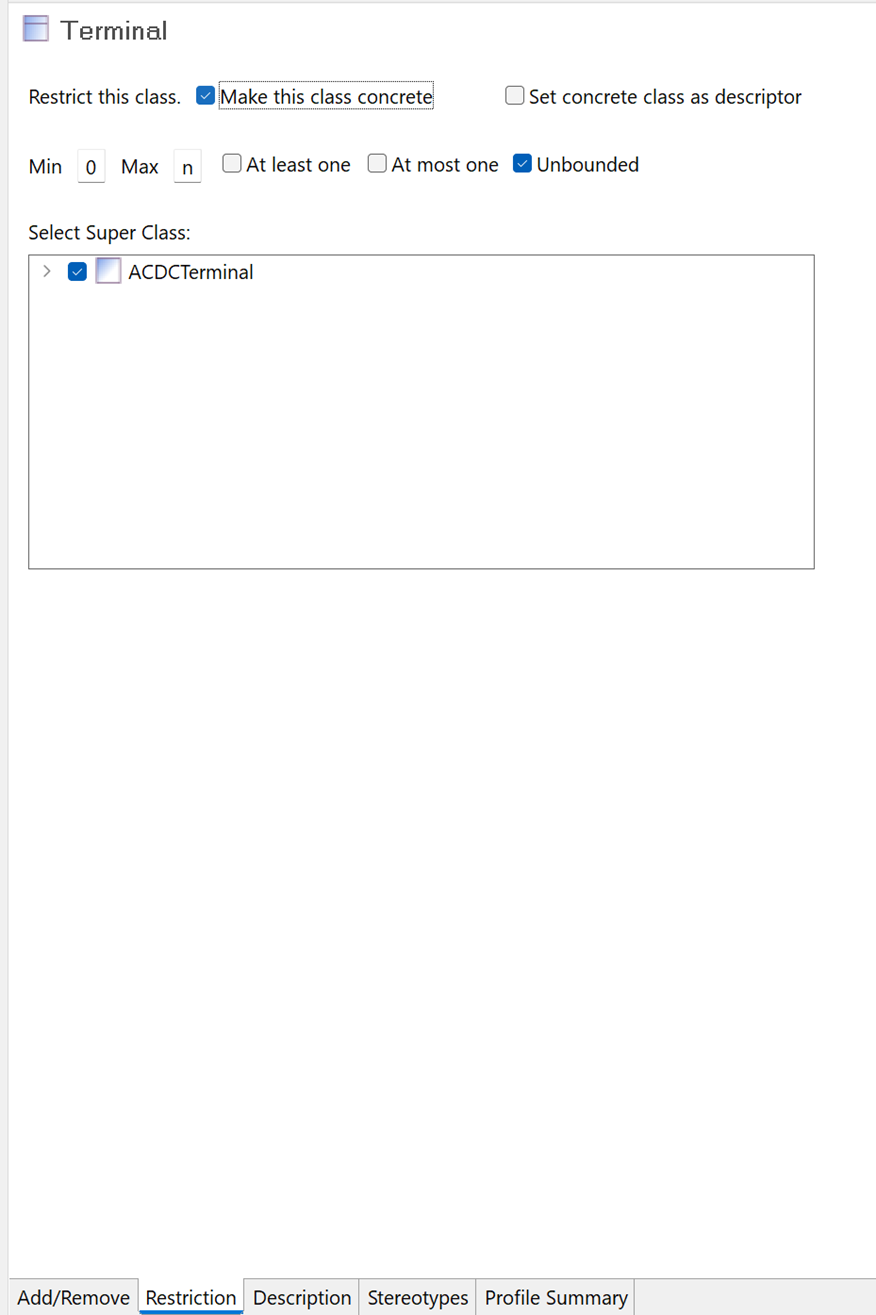
To add Terminal, the same steps as above will be performed. The class will be searched, the left arrow will be used to draw it into the profile, and from there things will look just slightly different. Since this is a concrete class, it must be set as such using the Restrictions tab in CIMTool.
As shown in Figure 7 6, Terminal was marked as a concrete class and a key visual for that is the appearance change of the icon next to Terminal. Now that Terminal is in the profile and is properly shown as a concrete class with ACDCTerminal as its Super Class (that is, the class from which it inherits its attributes), it is time to add some attributes and class relationships to it.
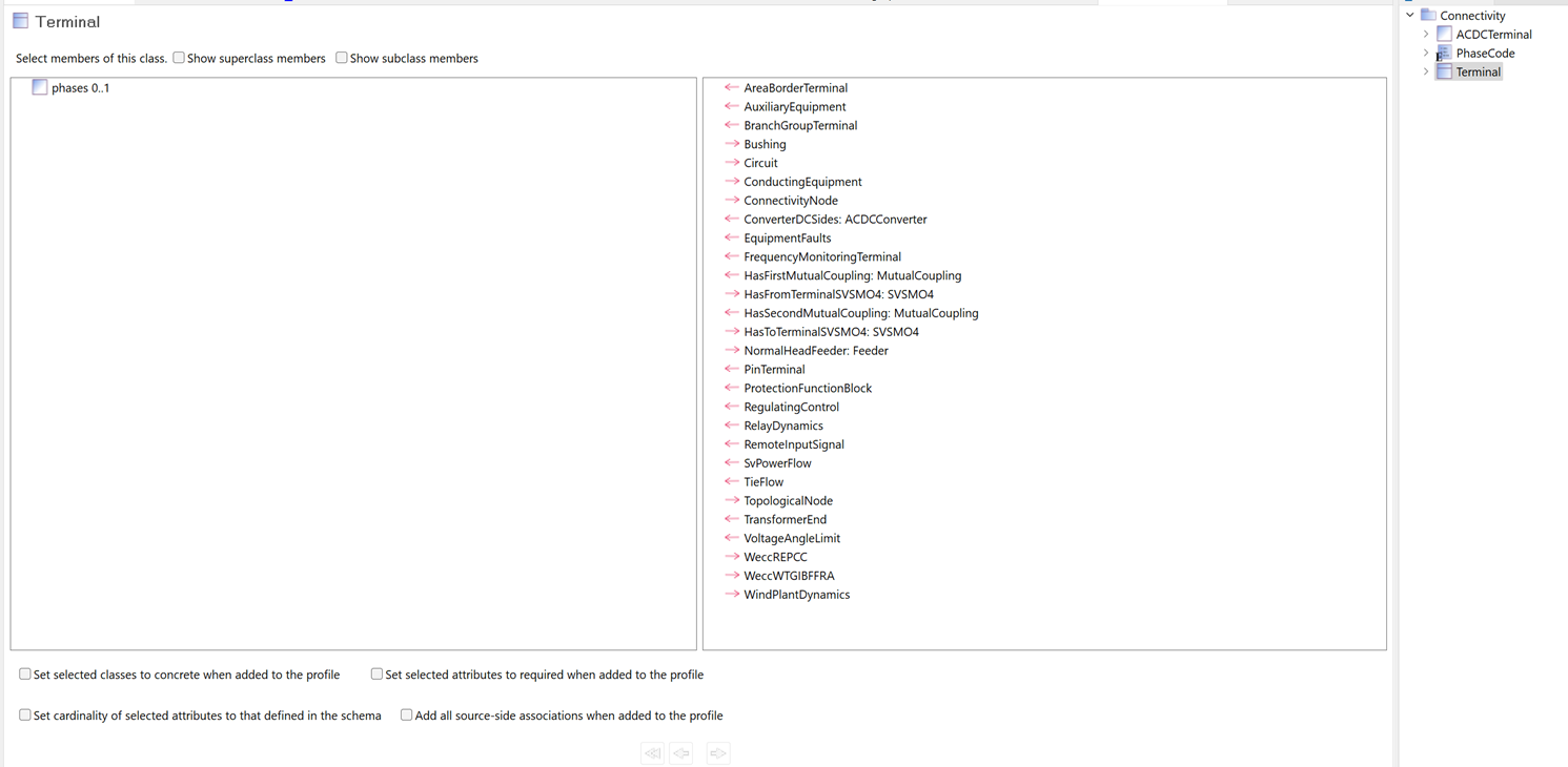
In this case, the only attribute that is being added to Terminal is phases. Since phases is an enumeration, adding it in CIMTool works slightly different. Enumerations in the CIM are modeled as classes, so not only does phases have to be brought in, but the PhaseCode class also must be added. To do this in the least amount of steps, simply use the double arrow icon to add this particular attribute.
Upon doing this, not only will this new attribute be added to Terminal, but as shown in Figure 7 7 there will be a new class added to the Outline for the profile as shown on the right side for PhaseCode.
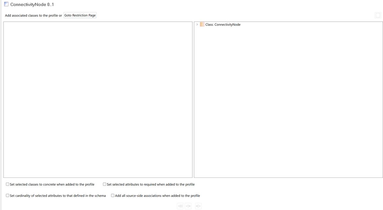
In addition to adding attributes, there are also other classes associated with Terminal that can be added on this screen. In the CIM UML, Terminal has relationships to many classes such as Feeder or ConnectivityNode. Despite the fact that RDFS defines bidirectional relationships between these classes, when creating the RDF schema in CIMTool, only class relationships denoted by the right arrow should be defined within that class. In other words, ConnectivityNode should be added here, but not Feeder. Instead, Feeder would add its relationship to Terminal.
To add this class relationship, let's first bring ConnectivityNode into the profile as shown in Figure 7-8 below. This will be a concrete class.
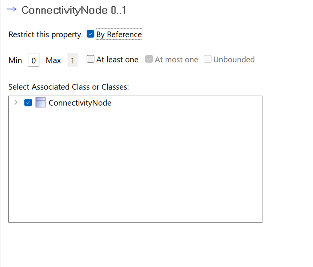
With that out of the way, go back to Terminal and add ConnectivityNode and after doing that, double click the ConnectivityNode within its Terminal definition to add further restrictions. It should look like the page shown below.
It is important to do a few things here. One is to check the box under Selected Associated Class or Classes. Only ConnectivityNode should be there for this example, but it’s possible for multiple classes to be here depending on the profile. Next, make sure to check the box saying that says By Reference to avoid any circular references in the schema.
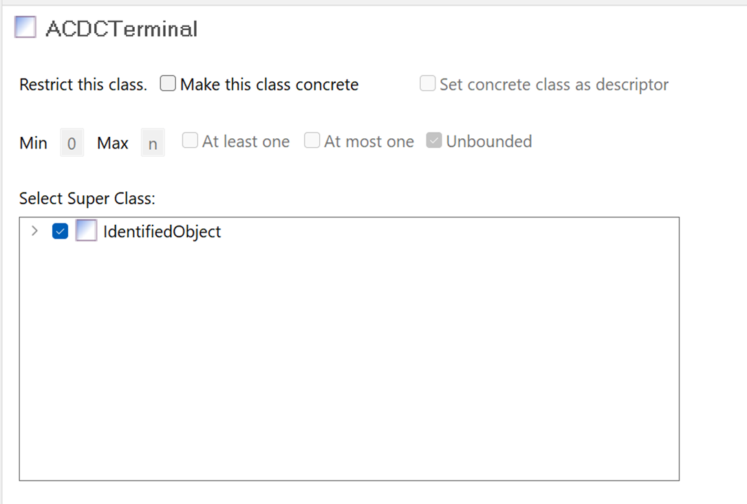
But wait a minute. Is IdentifiedObject going to be defined? Of course, but the order of doing so does not matter and once it is added in, the proper classes will automatically inherit from it. To demonstrate, this will be added next so that ACDCTerminal can inherit its attributes.
IdentifiedObject will be now be added following the same steps outlined earlier. It will have the attributes mRID, description, and name, with mRID being required. Upon being added, checking the restrictions page of ACDCTerminal confirms that it now inherits from IdentifiedObject and thus will have those same attributes.
Although this is far from a full profile, all the pieces are in place to continue adding onto it as needed to create a full Connectivity profile.
Generating RDF Schema
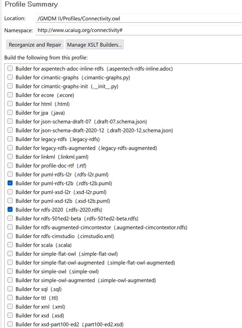
Now that the profile has been defined and the message structure has set, CIMTool will generate the required artifacts. As an RDF schema is desired, one of the RDF builders will be used to create the resulting RDFS file. In addition to that, one of the PlantUML builders will be selected to get a UML view of the profile to give a visual and confirm that it looks as expected.
As seen in Figure 7 13, there are many builders to choose from. For the RDFS itself, rdfs-2020 will give the most authentic modern version of CIM RDF. As for the PlantUML builder, RDFS and XSDs each have their own separate builders, with one marked l2r (right-to-left) and the other t2b (top-to-bottom). After selecting those and saving the profile, the artifacts will be created and shown in the Project Explorer. Before diving into the RDFS, first examine the profile’s UML and verify everything looks as expected.
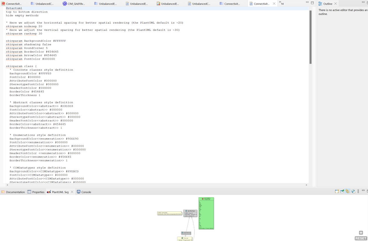
Right-click Connectivity.rdfs-t2b.puml and select the option to view it in the text editor. This should open a window with the text view of the UML, and the graphic view on the bottom of the screen.
On the bottom right-hand side of the screen, select the globe icon to open this UML diagram in the web browser instead, and it should then open in the default web browser for the PC. The UML of the profile described earlier should be shown.
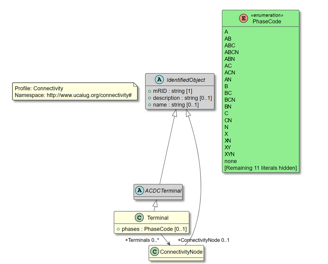
As seen in Figure 7 15, the correct classes are marked as concrete versus abstract and additionally, there are no red association lines, which would indicate an error in CIMTool. Everything looks great so far and now more classes can be added to the profile. With each change, simply save the profile to regenerate new PlantUML and RDFS, and repeat previous steps as needed until satisfied with the resulting profile.
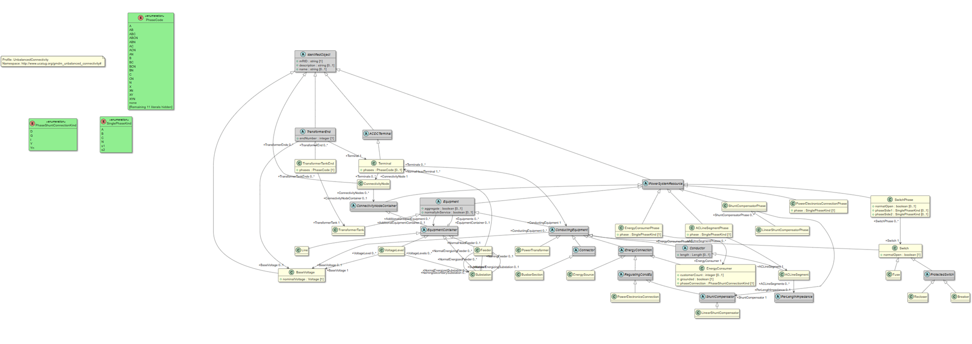
To show a finished profile example, below is a zoomed-out picture of the UML for the UnbalancedConnectivity profile.
RDFS Creation Summary
This example has shown how to create an RDF schema typically used for grid modeling. Real-world examples of this can contain thousands of objects and instance data so large that FTP is the preferred mechanism for transport. The format of these RDF messages in the CIM typically follows an RDF schema, and these can be generated in CIMTool in a manner that has some overlap with XSD creation but is different in ways that warrant a dedicated section describing its implementation. The CIM here provides a common semantic model, which provides the consensus on the interpretation of each class and attribute, removing ambiguity and duplication of definitions.
Case Study
As part of the CIM University course, Jeff Kimble has learned the details about how the CIM can support network model exchange. This is important as a utility models the state of the network and how it is configured. While the location and types of assets may not change frequently, the settings and configuration of the network is critical to having a proper understanding of how the network will perform. Often this information is communicated between utilities and the entities that are responsible for managing the interoperation of different regions, such as an Independent System Operator (ISO) or Regional Transmission Operator (RTO). This information may also be important for energy market operations (as was seen in this section with ENTSO-E).
However, Jeff learned that while the RDF schema can be very verbose, it is very powerful, flexible, and extensible. However, the drawback with exchanging an entire network model is that the size of the model can be difficult to manage. Due to the challenges with model size, the CIM specifications also include guidance on how to send a difference model that contains only the information that describes the changes between prior and current versions of the model. This ability to send only the changes between model versions has a tremendous impact on the size of the file that may need to be exchanged.
A simple way to think of serialization is that this is how data is represented in:
A
On a serial port
B
In a parallel file
C
On the front of a Wheaties box
D
In a file, or transmitted on the wire
D. In a file, or transmitted on the wire
The CIM difference model is used to:
A
Describes the differences between two classes
B
Describes the changes between two CIM RDF XML files
C
Describes the changes between two CIM UML files
D
Describe the difference between two message headers
B. Describes the changes between two CIM RDF XML files
While RDF can be very verbose, one of the benefits of this format is:
A
The files are very large
B
Additional elements can be added without ‘breaking’ parsers that rely on fixed formats
C
The files are much smaller
D
Unlike XML, RDF is self-describing
B. Additional elements can be added without ‘breaking’ parsers that rely on fixed formats
For model exchange, the abstract Model class and attributes are important because:
A
It uniquely identifies the model and reflects its state
B
It uses longhand syntax
C
The model class doesn’t concern itself with trivial information such as versions
D
The model class provides for compression
A. It uniquely identifies the model and reflects its state
The difference model provides a mechanism to allow _______ to a network model.
A
Additions only
B
Deletions only
C
Additions and Deletions
D
Additions, Deletions, and Updates
D. Additions, Deletions, and Updates
