
Learning Objectives
- Understand how CIM handles unique identities
- Understand CIM inheritance and see examples of class hierarchy
- Understand the basics of converting a circuit diagram into a CIM model
- Understand how the CIM incorporates geospatial information into the model
- Understand the classes of the CIM diagramming layout meta-model
- Understand the overview of CIM packages
Overview
The CIM is an implementation-agnostic model, defining information used by electric utilities in UML as classes along with the relationships between these classes: inheritance, association and aggregation; and the parameters within each class are also defined. This provides the foundation for a generic model to represent information, independent of any particular proprietary data standard or format.
For some readers, the format of the Common Information Model (CIM) may at first appear confusing compared with traditional flat file formats. In Section 4, UML was examined with classes and their relationships explored. This section will cover how the CIM uses UML to describe the components of a power system and how this is then expanded to model data related to the operation and management of the power system.
CIM Class Structure
The CIM hierarchy currently has no official common super-class (that is, a class from which every component inherits). The majority of CIM classes, however, inherit from the IdentifiedObject class so for this section it can be considered the base class for the hierarchy.
The reason for having a super-class is to have common attributes for identification that can be used by any class that needs to be given a universally unique identifier (commonly referred to as a UUID or GUID) known in CIM as a Master Resource Identifier (MRID) and a human readable name.
With the CIM v15 release, a construct was also added to enable any class that inherits from IdentifiedObject to have 0 or more additional Name entries using a 0..* association between IdentifiedObject and Name.

In the figure above the IdentifiedObject class is shown along with the Name class. In addition the NameType and NameTypeAuthority is also included. These latter classes are used to more accurately identify what an additional Name entries refers to. For example, a component may exist in multiple different systems with different identities depending on the application. This could be for a variety of reasons including:
- Naming limitations on the source system (that is, maximum of eight characters for a name)
- Historical divergence of data (two systems modeled the same network independently and now must be merged whilst maintaining the identity used on each system)
- To maintain local names from different utilities when network models are merged from neighboring utilities
The NameType class is used to identify what type of name is being provided. For example the NameType is description and the corresponding Name contains a verbose, human-readable description of the component. It may alternatively be pathname to indicate that the Name contains a value that represents a path for the component within the overall network hierarchy (that is, country/region/city/locale/substation/voltage/bay/name).
The NameTypeAuthority is used to optionally describe which authority issued this name. This could refer to an application for a systems integration environment or an organization if the data is coming from multiple organizations. For example a component may have a Name entry with a value on name that is of a NameType for name localName and has a NameTypeAuthority from ENTSO-E to indicate that it is the local name for the component as issued by ENTSO-E. It may simultaneously have another instance of Name assigned which also has a NameType with name localName but a NameTypeAuthority of EDF indicating that this is Électricité de France’s (EdF’s) local name for the component.
In versions of the CIM prior to v15 this Name/NameType/NameTypeAuthority construct did not exist and instead IdentifiedObject had additional attributes for pathName, aliasName, localName and description. The issue with this approach is that it limits an exchange to having only one alias and a number of situations arose where there was a need to exchange more than one alias for a component. The new approach added with CIM v15 allows for n additional aliases to be included and adds an additional level of description by making it clear where the aliases came from and their type.
Using Class Structure for Defining Components: Breaker Example
The breaker provides a simple example that can be used to explain why it is advantageous to use a class structure for defining components instead of simply specifying attributes for every different type of component in the CIM as an independent entry.
A Breaker is one of the most common components in a power system described in the CIM as:
“mechanical switching device capable of making, carrying, and breaking currents under normal circuit conditions and also making, carrying for a specified time, and breaking current under specified abnormal circuit conditions”
To understand how this fits into the CIM class hierarchy the Breaker can be thought of at different levels of abstraction.
At the most detailed level it is a Breaker, which itself is a type of switch that can be operated by Protection Equipment. At a more general level the breaker’s most basic functionality is the ability to be open or closed; therefore, it can be described as a specialized type of switch. Within the power system a switch is part of the physical network that conducts electricity, and as such can be considered a piece of conducting equipment. Since the power system may contain equipment that does not conduct electricity directly, conducting equipment can be considered a type of generic equipment. A piece of equipment can similarly be considered as a being resource within the power system.
A Breaker can therefore be considered to be a Power System Resource; a type of Equipment; a type of Conducting Equipment; a type of Switch; and a type of Protected Switch. This corresponds to a class inheritance structure shown in the figure below.
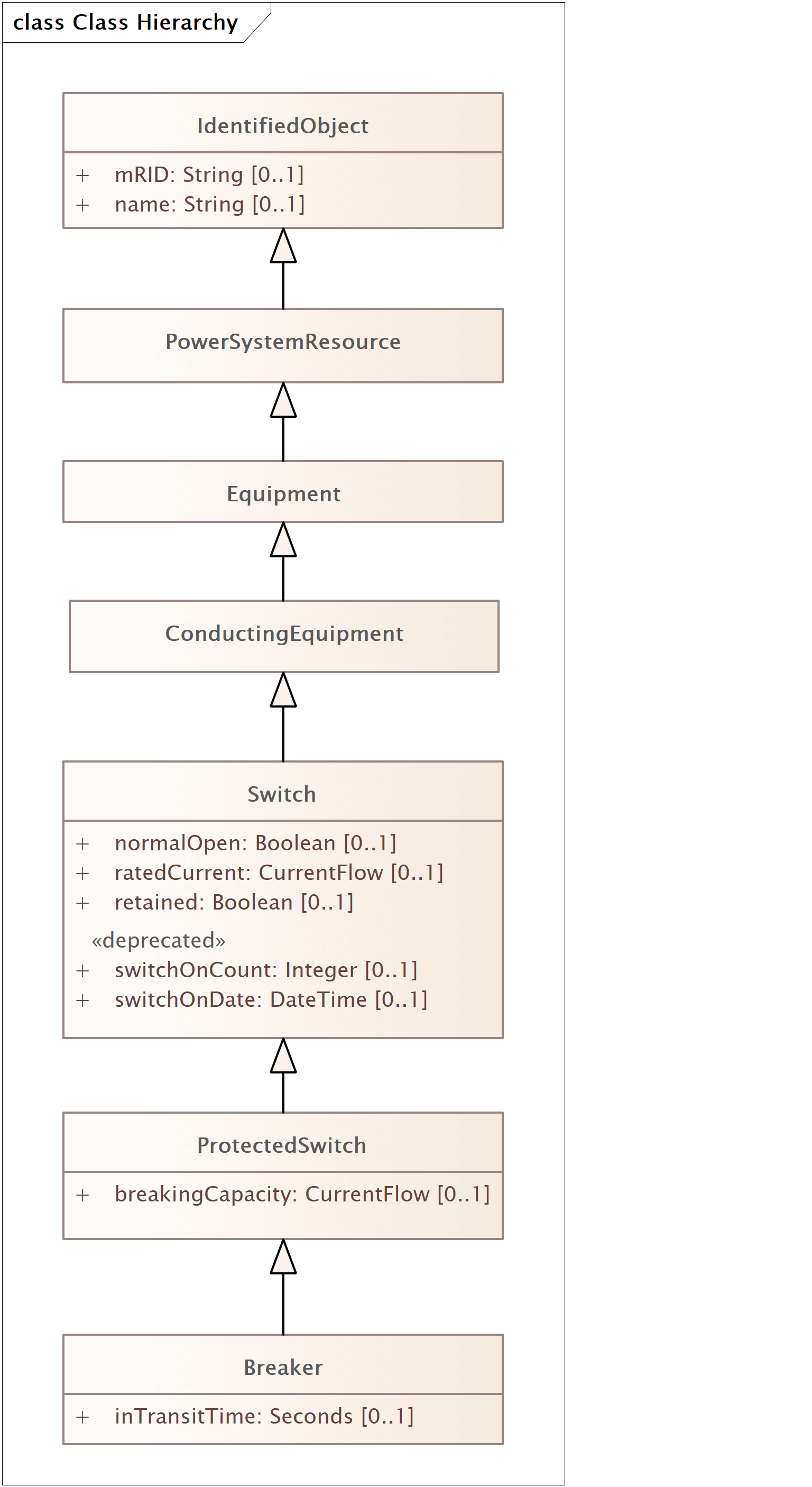
The IdentifiedObject class is the root class for this particular branch of the CIM class hierarchy and other CIM classes in the Breaker hierarchy are:
PowerSystemResource, used to describe any resource within the power system, whether it be a physical piece of equipment such as a `Switch* or an organizational entity such as aControlArea.Equipment, which refers to any piece of the power system that is a physical device, whether it be electrical or mechanical.ConductingEquipment, used to define types of `Equipment* that are designed to carry current or that are conductively connected to the network.Switch, a generic class for any piece of conducting equipment that operates as a switch in the network and hence has an attribute to define whether the switch is normally open or closed; its rated current; whether it is retained or not when the network is converted to a bus-branch representation;19 and attributes to record the number of types the switch has operated and the last date it operated.ProtectedSwitch, a switch that can be operated by protection equipment and has a breaking capacityBreaker, a specific sub type ofProtectedSwitch , with an additional attribute to define the transit time.
As with the Shape examples in Section 4, all subclasses inherit the attributes from their parent class, and as such a Breaker will contain a normalOpen, from the Switch class, and the name attribute, from the IdentifiedObject class, as well as its own native attribute.
Subclasses of Switch
As well as Breaker, the CIM standard contains multiple subclasses of Switch, including Jumper, Fuse, Disconnector, LoadBreakSwitch and GroundDisconnector.
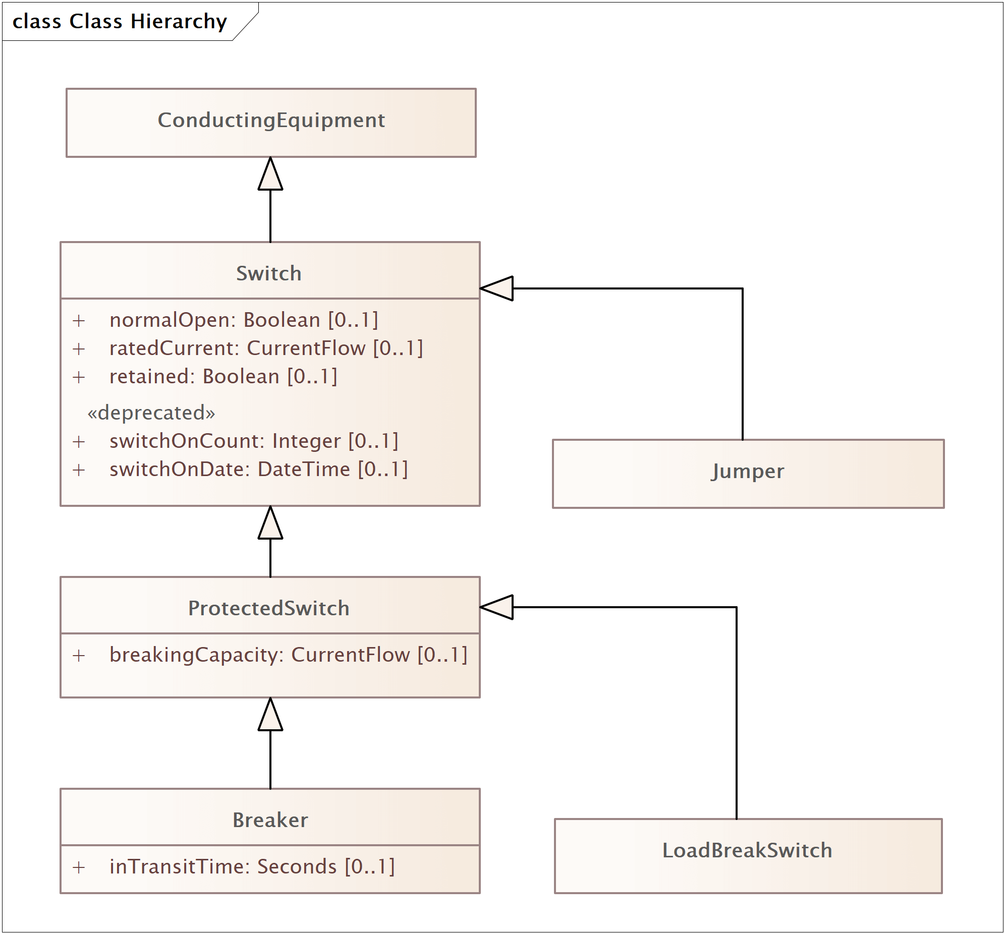
The figure above shows an example of how the LoadBreakSwitch class, a subclass of ProtectedSwitch fits into the class hierarchy along with Jumper, a subclass of Switch. Both Breaker and LoadBreakSwitch inherit from ProtectedSwitch, which in turns inherits from Switch along with Jumper. As such, Jumper, Breaker and LoadBreakSwitch all contain a normalOpen attribute whilst maintaining their own internal attributes. As well as dealing with them as their native class, the system can treat a Breaker or LoadBreakSwitch component as being a ProtectedSwitch, Switch, a piece of Conducting Equipment, a piece of Equipment, a Power System Resource or just an IdentifiedObject.
For example:
If a piece of software is performing a topological analysis on a power system network then it will need to know whether a switch is normally open or closed to determine the status of the network and calculate the buses (known as Topological Nodes in CIM). The software does not need to know whether the switch is a Breaker, a LoadBreakSwitch or any other subtype of Switch since the attribute it is concerned with, normalOpen, exists in all the classes that inherit from Switch. As the software traverses the network model, if the component it reaches is of the class Switch or any of its subclasses it extracts the value of normalOpen and continues accordingly.

If a new type of Switch, NewSwitchType is added to the standard at a later date as shown in the figure above, assuming the original Switch class is not modified, then the software will still be able to treat NewSwitchType, as if it were a Switch when performing its analysis. Even though the class did not exist when the software was originally written it is looking for any components that are of a class that inherits from Switch.
Similarly, if a new subclass of Breaker, NewBreakerType, is added (as shown in the figure above), it is still a type of Switch (since its parent class, Breaker is a subclass of ProtectedSwitch, which itself is a subclass of Switch) and can be treated as Switch, ProtectedSwitch or a Breaker by the software. In software engineering this is known as polymorphism.
As has been shown, this use of an inheritance hierarchy to define components allows classes within the system to be defined as specialized subclasses of a general parent class until the desired level of detail has been reached, from the generic PowerSystemResource right down to the Breaker or LoadBreakSwitch class.
This use of a class hierarchy also allows extensions to be made to the standard by extending the existing classes instead of introducing completely new, independent entries. This approach, as shown, can allow existing software applications to interpret the new data, albeit at a higher level of abstraction, without necessarily requiring extensive modification.
Defining Component Interconnections
When defining how components within a power system network join together, rather than define direct connection between components, the CIM uses Terminals and Connectivity Nodes. To understand why this approach is taken consider the very simple, circuit shown in Figure 5-5 below.

Figure 5-5 Connectivity Example Circuit
This circuit, containing a Breaker, Load, and Line, would require three CIM Objects to represent the pieces of physical conducting equipment:
An Energy Consumer (to represent the load), a Breaker, and an AC Line Segment for the line. The CIM does not model interconnections by associating each component with the other components it connects to, since having Breaker 1 associate directly to Load A and ACLineSegment Alpha; Load A associate directly to ACLineSegment Alpha and Breaker 1; and ACLineSegment Alpha associate directly to Breaker 1 and Load A would result in the interconnections being defined as shown in the figure below.

Figure 5-6 Connectivity Example Circuit with Direct Associations
Instead, the CIM uses a Connectivity Node to connect equipment, so that should three or more pieces of equipment meet at a T or Star point, the connectivity is accurately represented as shown below.

Figure 5-7 Connectivity Example Circuit with Connectivity Node
In CIM, however, pieces of conducting equipment are not directly associated with Connectivity Nodes. A piece of conducting equipment will have one or more Terminals associated with it, and these Terminals in turn are associated with a single Connectivity Node.

The relationship between the Terminal, ConnectivityNode and ConductingEquipment classes is shown above. Since only pieces of conducting equipment carry current on the network, the association to the Terminal class is from the ConductingEquipment class with cardinality 0..* meaning a piece of conducting equipment can have zero or more connections to the network.
The corresponding Terminal to Conducting Equipment relationship has cardinality 1 since a Terminal can only ever be associated with one piece of Conducting Equipment and cannot exist independently. Since the Breaker class (via its Switch class parent), Energy Consumer and AC or DC Line Segment (via the Conductor class) all inherit from Conducting Equipment, they too inherit the association relationship with the Terminal class.
The Terminal has an association to a single ConnectivityNode, and multiple Terminals may associate with a single instance of ConnectivityNode. By this mechanism electrical connectivity is defined as the ConnectivityNode is a zero impedance point of interconnection and all the Terminals that associate with a single ConnectivityNode are thus interconnected.
The connectivity relationship between the terminals, conducting equipment and connectivity nodes is illustrated in the figure below.

Figure 5-9 Connectivity Example Circuit with Connectivity Node and Terminals
The inclusion of the Terminals may initially seem unnecessary, but as well as defining connectivity, Terminals are also used for defining points of connectivity-related measurement in the network such as current flows and voltages.

Figure 5-10 Connectivity Example Circuit with Additional Breaker Terminal
Footnotes
19 For a description of how to convert CIM to bus-branch see the paper “Translating CIM XML Power System Data to a Proprietary Format for System Simulation”, A.W. McMorran, G.W. Ault, I.M. Elders, C.E.T. Foote, G.M. Burt, J.R. McDonald, IEEE Transactions on Power Systems, February 2004, Volume 19, Number 1, pp. 229-235.
Translating a Circuit into CIM
The previous sections have described a small section of the class hierarchy for describing CIM components and shown how Terminals and Connectivity Nodes are used to define the interconnection of components within the network. This section will use a more complex example to show how voltage levels, current transformers, power transformers, and generators are modeled by converting a standard line diagram into CIM objects.
Identifying CIM Components

The circuit shown in the figure above shows a circuit containing a single generating source, load, line, and busbar. The circuit also contains two power transformers resulting in three distinct voltage levels of 17kV, 33kV and 132kV.
The load, line, and breakers map to the CIM EnergyConsumer, ACLineSegment, and Breaker classes respectively while the busbar similarly maps to the BusbarSection class. Generator Alpha will map to a single piece of conducting equipment, the SynchronousMachine, an “electromechanical device that operates synchronously within the network” as defined in the CIM. When operating as a generator, the SynchronousMachine object must have an association with an instance of the GeneratingUnit class.
The GeneratingUnit class does not represent a piece of conducting equipment that physically connects to the network; instead, it represents “a single or set of synchronous machines for converting mechanical power into alternating-current” as defined in the CIM.

These mappings are shown above, leaving only the two power transformers and current transformer to be mapped to CIM classes.
Transformers Prior to CIM v15
Prior to 2011 the CIM Transformer Model had been relatively unchanged since its inception. The model reflected the typical EMS representation of a power transformer which is not mapped to a single CIM class; instead, it is split down into a number of components with a single PowerTransformer class. A two-terminal power transformer becomes two TransformerWinding objects within a PowerTransformer container. If a tap changer is present to control one of the terminals then an instance of the TapChanger class is associated with the TransformerWinding object of that particular terminal while still being contained within the PowerTransformer instance. The UML class diagram for the classes that form a transformer is shown in Figure 5-13 below.
")
Although a PowerTransformer is still a piece of Equipment in the system, in versions of the CIM prior to v15 the class itself does not inherit from ConductingEquipment but from its parent, Equipment. A TransformerWinding, however, does inherit from ConductingEquipment and it is through these classes that the PowerTransformer’s connectivity is defined. The TapChanger is part of the TransformerWinding and as such cannot be considered to be a separate piece of equipment in its own right and inherits from PowerSystemResource. In some later versions of the CIM, TapChanger was itself sub-classed into PhaseTapChanger and RatioTapChanger to represent the different tap changer types.
The PowerTransformer and TransformerWinding classes have an aggregation relationship20, meaning that a PowerTransformer is made up on one or more TransformerWindings which in turn can be made up of zero or more TapChangers.
When considering a physical transformer sitting in a substation the PowerTransformer container can be thought of as the shell of the transformer. The shell itself does not conduct any of the electricity in the network, but instead holds the windings of the transformer, the insulating material, magnetic core, and all the other components that make up the transformer.
The connections from the transformer to the network are made with the windings themselves, a relationship that is mirrored in the CIM representation where it is the TransformerWinding class that inherits from ConductingEquipment.

Thus, Transformer 17-33 from Figure 5-11 can be represented as four CIM objects: two TransformerWindings, one TapChanger and one PowerTransformer as shown in Figure 5-14 along with the Terminals associated with each TransformerWinding.
Similarly, a transformer with a tertiary or quaternary winding can be represented as a single PowerTransformer containing three or four instances of the TransformerWinding class.
Transformers After CIM v15
As the CIM has moved beyond its original roots in modeling balanced transmission networks into the distribution world there was a desire to create a single, harmonized transformer model that is:
- Suitable for phase balanced or unbalanced networks
- Suitable for representing unbalanced construction commonly used for low voltage distribution networks
- Allows for simultaneous representation of network components as both balanced and unbalanced depending upon the level of detail desired (that is, when performing detailed phase unbalance studies on nominally balanced high voltage networks, or for modeling the transition between balanced and unbalanced representations)
A group of experts worked on an update to the CIM transformer model to reflect these requirements, which was then integrated into the draft of CIM v15.
Changes to Transformer Model
There are a number of significant changes compared with the previous model that was described in the previous section:
PowerTransformernow inherits fromConductingEquipmentrather thanEquipmentso theTerminalsare now associated with thePowerTransformerrather than the windings as with the previous representation.TransformerWindingnow renamed toTransformerEnd. This is because the term winding was felt to imply that the model represented the internal configuration of the transformer, but in reality theTransformerWindingwas really describing the transformer’s terminals. Since the termTerminalis already used in the CIMTransformerTerminalwould have been confusing and ambiguous so the termTransformerEndwas used instead.- Additional classes were added to model transformer tanks, typically used in distribution systems where a single transformer contains multiples tanks each with its own
TransformerTankEnds. - The transformer impedance and admittance attributes as star or mesh explicitly. Previously these attributes appeared on the
TransformerWindingclass which meant that on a two-winding transformer the impedance between the primary and secondary windings would be put on the primary winding with zero values on the secondary winding. - Impedances and admittances can be defined once and re-used across multiple instances, reflecting the concept of catalogues of common values that are used across multiple instances in distribution networks. The ability to explicitly define impedance and admittance values on the
TransformerEndis still maintained.21 - The
TapChangermodel is expanded to explicitly model not only ratio and phase tap changers explicitly but also specializations ofPhaseTapChangerfor symmetrical and asymmetrical models.

The complete class diagram for the new transformer model is shown in Figure 5-15 and even with the Tap Changer model omitted it is significantly more complex than Figure 5-13. This does not mean that representing the same transformer in CIM v14 and CIM v15 requires a corresponding increase in complexity. The diagram reflects the two different potential routes to model transformers depending on whether they are for a balanced transmission system or represent multi-phase transformers (that is, pole-mounted distribution transformers) and when modeling a balanced transmission level power transformer the changes are minor.

Figure 5-16 shows the classes required to represent a balanced transmission level power transformer in CIM v15. This includes the new TransformerMeshImpedance and TransformerCoreAdmittance classes, which could be considered optional as the legacy explicit attributes for impedance and admittance are still included in TransformerEnd.

The corresponding instance example for CIM v15 is shown in Figure 5-17 where a PowerTransformer, two PowerTransformerEnds, a TransformerMeshImpedance, and a TransformerCoreAdmittance are modeled. In this diagram a RatioTapChanger has also been included, although this could also be a PhaseTapChanger, in CIM v15 they are explicitly defined as separate associations and there are multiple subclasses of PhaseTapChanger which are described later in this section.
The Terminals in this representation have an association to the PowerTransformer since it now inherits from ConductingEquipment, but there is also a direct association between TransformerEnd and Terminal (shown as the dotted line in the diagram).
At first glance the new transformer model appears far more complex than was present before CIM v15. However, the reader should see that representing the same data for a balanced transmission transformer requires only minor refactoring of the data elements and the inclusion of some new classes for more explicitly modeling impedance and admittance. These new classes for impedance and admittance are currently optional as the attributes for representing the impedance and admittance are still present in the new TransformerEnd class (however these are not used in the example above as they should be considered legacy or deprecated).
Unbalanced Distribution Transformer Model with Tanks

When defining an unbalanced distribution transformer, the PowerTransformer will contain one or more tanks, each with its own phase and two or more TransformerTankEnds. An instance example of this is shown in Figure 5-19 with a single PowerTransformer with two Terminals that is part of a three-phase system, but with three TransformerTank instances, each containing two TransformerTankEnds of a single phase. Both the Terminals have a phase code of ABC22 and a ConductingEquipment association to the PowerTransformer, but each Terminal also has three additional associations to the individual TransformerTanksEnds on each side of the transformer.
The TransformerTankEnds and PowerTransformerEnds from the previous example share references to a common Terminal instance but specialize the abstract TranformerEnd class and thus reuse the same representation of impedance schema. This means that the two models share common representations for the key electrical properties, the major differences being the inclusion of multiple tanks within a single PowerTransformer instance when modeling the distribution network; and the TransformerTankEnd specifies the phases of the tank, which must be a subset of the phases of the associated Terminal.
Thus, the Terminal represents the external connection of the PowerTransformer and the TransformerTank and TransformerTankEnd represent the internal model of the transformer and how it connects to the external terminals.
Tap Changer Model

The Tap Changer model shown in Figure 5-19 at first appears to be very complex but this is primarily due to the classes hierarchy. The concrete class are represented in red and the reader can see that the different types of Tap Changer remain as ratio and phase but with the addition of explicit Phase Tap Changer specializations for a linear tap changer and for the two types of non-linear tap changers: symmetrical and asymmetrical.
In addition, both phase and ratio tap changers may have tabular entries with multiple points. This allows the change in phase and/or ratio to be described as an explicit curve rather than as a linear change (or in the case of the non-linear tap changers, using standard formulae for tap changer behavior). These classes, shown in green above, allow both ratio and phase tap changers (including all subclasses) to have a single <Ratio/Phase>TapChangeTabular entry and multiple TapChangerTabularPoint entries. Each entry contains attributes for the impedance, admittance and step with the ratio or phase angle depending on the type.
Equipment Containment
As well as having component interconnections defined using the ConductingEquipment-Terminal-ConnectivityNode associations, the CIM has an EquipmentContainer class that provides a means of grouping pieces of Equipment together to represent both electrical and non-electrical containment.
Voltage Levels
Pieces of conducting equipment generally do not have a voltage attribute to define the voltage as a specific value, instead they are associated with a VoltageLevel, a subclass of EquipmentContainer. Each instance of the VoltageLevel class has an association to an instance of BaseVoltage that contains a single attribute to define the nominal voltage of that particular group of components. A single BaseVoltage instance exists for all of the standard nominal voltages used within the data. As such they may be associated with more than one VoltageLevel since standard voltage levels (that is, 33, 132, 275, 400kV) will exist throughout the network. Each VoltageLevel instance, however, contains only the interconnected pieces of equipment at the same voltage level. This is an example of using a subclass of EquipmentContainer to represent electrical containment.
Substations
The Substation class is a subclass of EquipmentContainer that can contain multiple VoltageLevels and is used to define a collection of equipment “through which electric energy in bulk is passed for the purposes of switching or modifying its characteristics” in the CIM.
In the example network shown in Figure 5-11 the three different voltage levels identified by the dashed bounding boxes are mapped to three instances of the VoltageLevel and contained within a single Substation instance. Each VoltageLevel object also has an associated BaseVoltage object with a nominal voltage of 17, 33 and 132kV.
The Substation class, being a subclass of EquipmentContainer can also contain other instances of Equipment, such as PowerTransformer, which as previously explained, was itself a container, not a piece of conducting equipment in CIM prior to version 15. The Substation class is an example of a subclass of EquipmentContainer to represent non-electrical containment since it will contain pieces of equipment that are physically grouped, but not necessarily electrically connected.
Lines
The ACLineSegment is not contained within a VoltageLevel. Instead it is contained within an instance of the Line class. The Line class in CIM is used to define a “component part of a system extending between adjacent substations or from a substation to an adjacent interconnection point”. A Line may contain multiple line segments of either the AC or DC variety, but does not itself represent a piece of physical conducting equipment.
Since a line segment is used to represent “a wire or combination of wires … used to carry alternating [or direct] current between points in the power system” so it would be inaccurate to define it as being inside a specific voltage level within a substation. As such, the AC and DCLineSegment classes contain a direct association to the BaseVoltage class to define their nominal voltage level.
In transmission models the Line class generally contains only ACLineSegments and ConnectivityNodes however when used in the distribution networks it may contain all equipment considered to be within a feeder such as switches and transformers.
Units and Language
Data Type Units
As an IEC standard the CIM requires that all units must be defined as SI or SI-derived. This means that in the CIM values are not expressed as per-unit which is very common for power system formats. All distance and volume measurements are metric and temperature in Celsius23, and so on.
The CIM defines data types for all units used and are defined in the UML with a stereotype of CIMDataType. For numeric units there is also the option of defining a standard multiplier along with the default unit. This means that values that are commonly in the thousands or millions can have a default multiplier of kilo or mega added thus allowing voltages to be kilovolts or power as megawatts reflecting the common representations within the industry without breaking the rules requiring SI units.
Enumerations
A number of attributes are defined as having an enumerated type.
An enumeration is a list of pre-defined values and the value of these attributes must be one of these values to be valid. Examples of enumerations include the phase code (A, B, C, AB, AC, ABC, and so on) or the operating mode of a Synchronous Machine (generator or condenser).
Language
As an international standard the CIM is written in English, but even though it originated in North America, the IEC require the use of British English. As such all CIM terms are defined in British English terms, resulting in terms that, to American users, may appear misspelled.

Figure 5-20 shows the CIM representation for the circuit shown in Figure 5-11. The BusbarSection’s position may at first seem erroneous, but in the CIM the ConnectivityNodes are used to define the point of interconnection for pieces of equipment. As such, the BusbarSection object is used primarily to provide a point of association (via its Terminal) for Measurement objects measuring the voltage at that particular bus-bar in the system. This reflects the positioning of equipment in the physical system, since a voltage transformer will often measure voltages at the bus-bars within a substation.
The current transformer (CT) in the original diagram does not map to a piece of ConductingEquipment in the CIM. Instead a Measurement instance, representing a SCADA measurement from the CT is associated with the Terminal on the Breaker. Since the CT does not impact on the electrical characteristics of the network and affect the results of any analysis, it is not explicitly modeled in the same way as a breaker, generator, load, and so on. There may be a need to know about the physical piece of equipment that is in this place in the network, but this is the Asset view of the system which will be discussed in the next section.
This representation of the example network could be extended further with the addition of objects to represent control areas, equipment owners, measurement units and generation/load curves, but for now it is enough to understand how an existing network representation can be mapped to CIM objects.
Footnotes
20 Although it could be argued that this relationship is composition rather than aggregation the CIM class structure contains no composition relationships. This is due to the flexible design of the standard, where a composition relationship would indicate a tighter relationship between classes than is necessary for a number of applications of the standard.
21 The concepts of balanced/unbalanced, catalog/de-normalized, and impedance representation as star or mesh form are in theory completely orthogonal in the CIM information model. In practice the balanced and de-normalized star impedance are used together for transmission exchanges and the unbalanced and catalog features are used in distribution model exchanges.
22 They could also be ABCN to denote that the neutral is included.
23 Although it could be argued of course that Kelvin would be the purest definition of temperature.
CIM Supports Both Asset and Functional Views
Until this point the focus has been on the CIM’s representation of the functional electrical network as seen by an EMS or DMS and applications that analyze the electrical network. This is independent of the physical assets that fulfilling these functions on the network since a power-flow application is concerned with the function a piece of equipment provides; not its make, model and serial number.
As the CIM expanded from its roots in EMS there was a need to include such information, which is of vital importance to systems concerned with Asset Management, Work Management, Procurement, and so on. There is a need to both represent the physical asset and link to the function (or functions) it is performing from an electrical network perspective.
Modeling the Asset View
In the CIM there is separation of asset from role but with a linkage between the two perspectives. The asset view is concerned with how a piece of equipment is tracked, monitored, maintained, and so on from the perspective of procurement, maintenance, accounting, and so on. This view of the network includes the manufacturer, model, purchase date, installation date, maintenance history, and so on, but is generally unconcerned with how the asset fits into the electrical network beyond knowing its physical location.
Assets will also exist without being connected to the functional network view of the enterprise. They may be because some assets are not electrical equipment (that is, trucks, buildings, tools, and so on) or because they are not in commission and sitting in a warehouse or service yard. The asset management system must still have a record of these assets and track them from the point of ordering through their entire life within the organization. The asset may also move its position in the network, performing the same function but at a different location. The asset serial number does not change, but it is now linked to a different functional location in the network, which itself will have a unique identifier independent of the asset fulfilling the role.
The link between the CIM’s Asset class and the functional network is done via an association between PowerSystemResource and Asset as shown in Figure 5-21. When this association is fulfilled, the user can navigate from an instance of PowerSystemResource such as a PowerTransformer or Breaker to the Asset record that is fulfilling that role.
Benefits of Modeling an Asset View
A major benefit in this approach is that the replacement of a physical asset does not require the functional equipment entry to be altered. For example, take the situation where a breaker is to be replaced in the field. From the point of view of the operators of the network there will be a period of time where that part of the network is de-energized while the work is carried out and then it will be reconnected. From the perspective of the DMS or EMS, nothing fundamental has changed; there is still a breaker at that point in the network.
In some companies there has been cases where there is no distinction between functional and asset views in the system that maintains the network model. When a breaker is replaced the user deletes the previous breaker, inserts a new one, fills in the appropriate data, reconnects the terminals and the update is generated. This has caused problems where a system concerned with only the functional network view has a deletion and insertion of components that are, from a functional view, identical, but breaks linkages to other systems that were tied to the unique identifier of the previous breaker.

For example, looking at Figure 5-22 provides an example of a Breaker with an association to both of its Terminals, a Measurement, and the Asset with ID 9780-342 that has been fulfilling this role on the network since 3rd September 2006.
If the asset is to be swapped with a new one the linkages between the Breakers, its Measurement, and Terminals must not be lost. Additionally, its name or mRID should not be changed as this would also break the linkage. As such the functional Breaker instance is not altered, instead the association is changed to the instance of Asset that reflects the new piece of physical equipment.

The resulting associations, shown in Figure 5-23 have the Breaker instance associating with the new Asset instance with ID JA0923AJMUK and the previous association to the old Asset is removed. Those systems concerned only with the functional model that were linking to the Breaker and using its mRID are unaffected.
Understanding these CIM capabilities helps utilities work with system vendors and systems integration partners to ensure that asset management systems and operations systems can coexist and interoperate well. CIM offers a level of modeling that ensures, if model-driven integration is deployed, that enterprise applications will work well together. All necessary views of an asset are represented, throughout the life cycle of assets and in all operational scenarios.
CIM Supports Network Diagram Layouts
The ability to visualize network schematics can be critical for engineers when interpreting the status of an electrical network. As the number of systems utilizing electrical models grows and utilities move towards a single, common network model across applications, there is a need to ensure single line diagrams and other schematics are reproduced accurately across each system.
The diagram layout portion of the CIM provides a mechanism for describing the layout of electrical schematics. The diagram layout classes allow graphics and network data to be exchanged simultaneously, thus ensuring that schematic views are synchronized with the electrical model across multiple systems. This allows each system to recreate the layout of a schematic accurately while using their own styling for icons, colors, fonts and other graphical rendering attributes.
Separating Style from Layout
A key driver of the diagram layout model was that any receiving systems should be able to draw a schematic in the style that its users are familiar with. A SCADA system may use different icons, coloring and line styles than an EMS, but the operator will want to ensure that the layout of a substation, the position of bus-bars, switches and transformers is the same as in the EMS. With this use-case in mind, the diagram layout model is focused on the exchange of layout information allowing a graphic to be created, rather than the exchange of a graphic on which layout information must be derived.

As such each element that is to be rendered will have a corresponding Diagram Object, which can have one or more points to describe its location on the schematic. For many elements this is a single point defined as being the center of the object’s icon, as shown in Figure 5-24. Here each element itself has only a single point, with another Diagram Object and point used for each Terminal if it must be rendered on the screen.

More complex layout information, such as line routing, is accomplished with multiple points for a single Diagram Object as shown in Figure 5-25. As with the single point objects, each Terminal may have its own Diagram Object if required.
It is up to the receiving system to determine what icons they wish to use, what thickness a line should be and what color to use to ensure the graphic produced is familiar to the user.
Functional Model Integration
Extending the CIM to support Graphics Exchange allows the diagrams to be tied directly into the electrical model and can be stored and exchanged using existing CIM-compliant applications and formats such as CIM RDF XML which will be explored in Section 7. There are two major benefits to this approach:
-
Synchronization
By directly tying the schematic data to the electrical model data using the CIM, the exchange of schematic and network models is closely synchronized. This avoids the situation where something is changed in one system without a corresponding change appearing in the other due to there being no direct link between the data in each system.By modeling the data in CIM, existing data exchange formats can be leveraged, allowing the network model exchanges to include the schematic data directly. By ensuring a network update always includes the corresponding schematic update, all systems can ensure their displays are kept synchronized with each other and the electrical model.
-
Duplication of Data
By having a direct link between a schematic Diagram Object and the corresponding electrical model component the amount of schematic data that needs to be exchanged can be drastically reduced. For a receiving system to render a schematic the icons, coloring, line thicknesses and other styling information is based on the electrical properties of the element, so can be derived from the underlying electrical model.For example, the schematic data for a
Breakerneed only include a singleDiagram Objectand point since its icon will be dependent on its current position, normal position, voltage, and type, all of which can be derived from the electrical model and theBreakerelement the Diagram Object is associated with.By deriving information from a single source, the duplication of data is avoided between systems while helping the graphics derived from the schematic to be synchronized with the underlying network model.
Diagram Layout in UML
The diagram layout model is defined in UML and since CIM v15, has been part of the CIM UML. The class model is shown in Figure 5-26 with the previously discussed DiagramObject class in the center, and DiagramObjectPoint providing one or more spatial points to define an object’s location.

The other classes allow more complex layouts to be exchanged including layers, differing orientations with ascending or descending vertical axes, and to allow the sender to mark specific points, from multiple elements as glued points where a change in one may affect the others (that is, at points of interconnection).
While the standard is not intended to define a new standard for exchanging styling information when existing standards such as Cascading Style Sheets (CSS) can accomplish this, it does allow the style of a Diagram Object to be referenced. This is to allow two or more parties to agree on styling references using unique identifiers should they wish to.
The model allows for a single domain object (anything that is a subclass of the CIM’s IdentifiedObject class) to have multiple Diagram Objects. This is to allow the same element to exist on multiple diagrams, but to also allow for a single element to have multiple Diagram Objects within a single diagram (that is, an icon and a text label).
Having the ability to integrate the schematic layout data with the electrical network data will help users ensure their diagrams are synchronized with their network model, while enabling them to utilize existing exchange formats and technologies. The diagram layout model offers a lightweight solution to this problem, providing a common, vendor-neutral format that will allow systems to re-draw a diagram while maintaining its layout.
Embedding Geographical Data
The CIM also contains classes to define the geographical location of functional equipment or assets via the Location class that is very similar to that of the CIM Diagram Layout. The classes, shown in Figure 5-27 provide a construct similar to the diagram model, but with the addition of an explicit CoordinateSystem class with an attribute to denote the coordinate reference system. This uniquely identifies the coordinate system being used (that is, Latitude Longitude with Decimal Degrees, Lambert I-IV, GB Ordnance Survey Grid Codes, and so on).

Each Location can have one or more PositionPoints, which contains an X, Y, and optional Z coordinate to define a point in space. The Location class has associations to both Asset and PowerSystemResource and so can be associated with either.
The reason to associate the class with Asset is quite obvious since a physical asset is going to have a geographical location, whether it be in a substation or sitting in a warehouse. There are two primary reasons for associating it with PowerSystemResource as well:
-
In some exchanges of network data, especially with external organizations there is a need to send the geographical layout of the network, which may be in a simplified equivalent form, but the receiving party is not authorized to view the company’s asset data.
-
During the design phase for a network extension the functional network will be built with geographical routing data which will be needed to calculate costs, rights of way, and so on. At this stage there is no asset with which to associate the
Location.
The CIM Location classes have been successfully tested at both transmission and distribution level and provide a simple mechanism for exchanging the geographical location both from a functional and asset view.
Modeling Unbalanced Multi-Phase Networks
The CIM network model described in this section has focused on balanced, three-phase systems which are exchanged at the transmission level. For low-voltage distribution systems, however the balanced representation is often insufficient as there are many single phase loads which results in an unbalanced power-flow on three-phase devices.
There were a number of requirements that drove the CIM to be extended to more accurately model unbalanced three-phase (or two-phase) systems.
Measurements
A key requirement for modeling the individual phases is to be able to associate SCADA measurements with the individual phase devices. This allows the individual measurements (that is, current, voltage, reactive power, tap position, switch status, and so on) to each phase.
When there is a single device in the CIM with a single measurement it implies the device is balanced and all three phases have the same value (although in some cases the SCADA system may only measure one phase).
Three Phase Switches
Although normally modeled as a single device in the CIM, a three-phase switch (including subclasses like breaker and fuse) is actually composed of three separate physical switches, one for each phase. In the majority of cases each switch has identical physical properties, but it may be possible that each phase may have different characteristics.
As an example, in the case of a fuse there may be different ratings placed on the fuses for different attributes. There may also be changes in the response time and thus real-time status of switch statues as a result of these physical differences.
For gang operated switches the physical design of the switch enforces the synchronized state changes, but for un-ganged switches there may be situations where the normal and/or real-time operational state for each phase could be different.
In normal circumstances an operator wants to see a single logical switch with all three phases the same, but under certain conditions there would be a need to view each phase independently so they could be operated or monitored more precisely.
For asset information there is a need to tie each phase’s device to the physical asset that fulfills the role when that asset has attributes that impact on the operation of the device.
Three Phase Transformers
As was seen in the previous section, the requirements for modeling transformers in unbalanced systems has resulted in a detailed, complex transformer model that supports the modeling of a transformer’s internal configuration in three-phase, unbalanced systems.
Loads
There is a need to specify individual single-phase loads and three-phase loads where the individual phases do not have the same characteristics.
Lines
For unbalanced three-phase systems there is a requirement to accurately define the individual conductor parameters for each phase and their spacing. This is to allow unbalanced power-flow engines to create the impedance matrices for the unbalanced lines. In distribution systems it is common to define catalogues of values that are re-used across hundreds and thousands of instances, thus allowing a single type of conductor to have its parameters defined once (on a per length basis) and then applied to every line that uses that conductor.
In some cases, the conductor types may differ for each phase on a three-phase line so there is a need to be able to identify the phases on the line; associate them with the different conductor types, and define the spacing geometry. This does not require individual Terminals and ConnectivityNodes as the overall connectivity and topology of the network is common for each phase.
UML for Unbalanced Network Components

Figure 5-28 shows the resulting CIM UML for describing the individual phase components for AC Line Segments, Switches, Energy Consumers (Loads) and Shunt Compensators. Each follows a common structure where the Phase class inherits from PowerSystemResource and so inherits all of its associations, including the association to Asset, AssetInfo (and thus WireInfo and CableInfo) and to the Measurement class (which represents a SCADA measurement point).
Each of the Phase classes has one or more attributes to define the individual phase the instance represents, and for the SwitchPhase class there are two attributes to allow a switch to span between two phases. Additional attributes are then added for the other classes to describe the per-phase values as appropriate.
These classes may be expanded in the future if there is a requirement to model other CIM electrical devices for unbalanced three-phase networks.
CIM Packages Overview
As with any other complex class structure, classes in CIM are grouped together into packages24 dependent on their role within the utility. For a detailed view of all the packages, their classes and relationships the reader is urged to view the CIM UML model available to members of the CIM Users Group as an Enterprise Architect file or in the relevant IEC standard publications. This section will provide a brief summary of the three different standards that constitute the CIM UML.
IEC 61970-301
The core IEC 61970-301 standard contains a number of main packages, along with a global domain package used for defining data types. The Core, Wires and Topology packages contain all the basic classes for defining the physical characteristics of a power network.
The Wires package defines classes that are required to represent the electrical components of a network, such as Transformers, AC Line Segments and Switches, while the Core and Topology packages define the interconnection and containment of components.
These three packages alone however, do not fully describe a functioning power system, but provide only the basic electrical characteristics of the equipment and describe how they are connected. To provide a detailed description of a network at an operational level, other classes are required to define the data required for operation and control including: generation data, operational limits, SCADA measurement, state variables, and protection. Most recently IEC 61970-301 has seen the addition of the Diagram Layout classes for defining the layout of diagrams linked to the electrical network data.
IEC 61968-11
IEC 61968-11 extends the IEC 61970-301 model and introduces the classes aimed at the exchange of data within distribution companies. This includes extensions to the electrical network model to cover the requirements of distribution networks. The model also extends the CIM with the support for Asset Management, Customer Management, Work Management, Meter Data (including remote meter readings and meter data management) and Geographical Data.
IEC 62325-301
IEC 62325-301 builds on IEC 61970-301 and IEC 61968-11 and adds packages for defining the data exchanged between participants in electricity markets. These classes include the data exchanges at the different stages of market operations including: billing, clearing, and settlement.
The IEC 62325-301 classes do not themselves model a market, they are used to define the data exchanged between entities involved in the operation of the market so include classes to describe agreements, invoices, prices, bids, notifications, and so on.
Footnotes
24 A package is used to “group elements, and to provide a namespace for the grouped elements” (OMG Unified Modeling Language (OMG UML), Infrastructure, V2.1.1 p.158.) A package may contain other packages and provides a hierarchical organization of elements within UML.
Case Study
Jeff Kimble arrives at his first CIM Users Group meeting. One the first day he attends what is known as “CIM University”. This is a one day workshop where presenters hit attendees with what can only be described as “a firehose of information”. In one day attendees get an introduction to the CIM UML, the tool that is used to maintain it (Sparx Systems Enterprise Architect) so that they also learn how to search the model for items of interest, how to navigate the packages, and the many diagrams that are contained within the model that highlight certain relationships and ideas, for example, metering, or circuit models.
Jeff learns that there are hundreds of classes, thousands of attributes, and many relationships between the classes that is a very robust representation of the utility world. Each class also contains a description of what it is used for, so the model is also a form of a data dictionary, which Jeff learns is referred to as a “semantic model”. In addition to these many diagrams, Jeff learns that there is a thing called a “profile.” A profile is a “subset of the model, used to perform meaningful work, such as used to define a message”. These profiles then may describe a circuit diagram but may also be used to create a message that can be sent from one system to another.
Jeff learns that these profiles can be expressed syntactically as either XML or RDF. RDF tends to lend itself well to network model data exchange because the RDF intrinsically expresses data in graph form. He also learns that the XML profiles lend themselves very nicely for message definition; in fact there are dozens of profiles that can be used for messaging that have already been defined, and in many cases, have had interoperability testing performed by several vendors, some of which are used at IEU.
Jeff decides that he needs to learn which vendors support these CIM interfaces and how he can accelerate the migration to a CIM-based semantic model that is used at the enterprise service bus.
The `IdentifiedObject` class is used in the CIM to:
A
Determine which class that has been identified
B
Determine which object has been identified
C
Provide a globally unique master resource identifier
D
Provide a globally unique master class identifier
C. Provide a globally unique master resource identifier
The `NameTypeAuthority` is used to:
A
Provide the authority to identify classes
B
Determine the types of names that can be used for a class
C
Describes the type of authority for identifying classes
D
Used to identify the organization that creates Names for the Names class as an alternative to using IdentifiedObject
D. Used to identify the organization that creates Names for the Names class as an alternative to using IdentifiedObject
If the relationship between `ConductingEquipment` and `Terminal` is denoted as 1..0* respectively, this indicates that:
A
For each conducting equipment there are 1 or more terminals
B
For each conducting equipment there are 0 or more terminals
C
For each terminal there are many ConductingEquipment
D
For each terminal there are 0 ConductingEquipment
B. For each conducting equipment there are 0 or more terminals
The CIM has a mechanism for storing where assets are located via the _______ class.
A
GPS
B
Location
C
CoordinateSystem
D
StreetAddress
B. Location
Question - In the CIM hierarchy, a breaker is:
A
A PowerSystemResource
B
A ProtectedSwitch
C
ConductingEquipment
D
All of the above
D. All of the above