Learning Objectives
- Understand the CIM Interface Reference Model (IRM)
- Understand how to derive CIM profiles
- Understand the difference between the information, contextual, and information models
- Understand the main components of the Common Distribution Power System Model (CDPSM)
Deriving Profiles
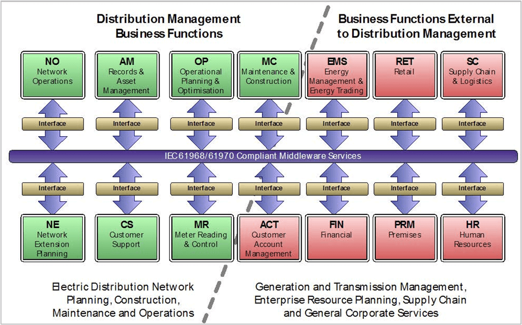
The CIM is by definition intended to be a single, “common” model. One of the key goals of the CIM is to prevent duplication of data definitions but still define all the data exchanged between the systems within organizations supporting electric grid systems. The IEC 61968 standard includes an Interface Reference Model (IRM, shown in Figure 6-1). This diagram illustrates the breadth of the model itself. The CIM has grown from an initial core set of less than 100 classes to describe a balanced electrical model for EMS, to a model with over 1,000 classes and thousands of associations and attributes.
Currently the IRM is being revised to combine both 61968 and 61970 business functions. The current work in progress is shown in Figure 6-2.
The scope of the CIM can be discovered in several ways:
- Reading the documents containing the IEC standards
- Viewing the UML model itself with Sparx Enterprise Architect or another tool
- Viewing the model in XML Meta Interchange (XMI) format with an XML viewer
Regardless of how a first-time visitor approaches the CIM, the model can appear unmanageably complex or even impractical, because every class and element is included. It’s important to understand that contextual modeling can simplify the CIM and make it extremely practical and manageable as project teams move from design on into implementation.
Moving from Information Modeling to Implementation
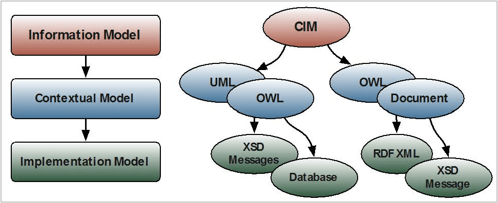
The CIM must be viewed as an information model, not an implementation model. The relationships in the CIM are generalized and are 0..1 or 0..n, and all attributes are considered optional. This can result in multiple ways of expressing data in CIM, all valid, but potentially resulting in incompatible implementations downstream in the project delivery lifecycle. As such, the reader must understand the role of profiles. To effectively adapt the CIM model for a specific context, CIM users can apply a profile. A profile is defined as a subset of the full model that serves to define the data exchanges required for target interfaces. Each profile is a collection of classes, attributes and references along with additional restrictions such as making attributes mandatory or restricting the cardinalities on associations.
This contextual model is then used to derive implementation models which define the serialization structure for the data. This could be a database schema, an RDF Schema, an XML Schema, or a JSON Schema. There are different formats for defining the contextual model depending on the tools being used, but the overall approach is common to all.
Contextual Models Simplify without Definition Compromise
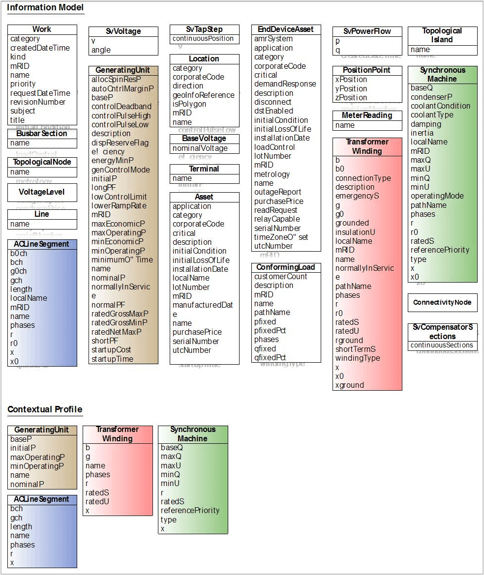
When viewed as its profile, a CIM interface is no longer a complex model of hundreds of classes, but is instead a small, select number of classes with the subset of their attributes and associations. When multiple interfaces are to be implemented by a single system, the practice of using profiles derived from a single overall model ensures that data definitions are re-used (and duplication is prevented). For example, a GeneratingUnit is defined once in the CIM but can be used in any number of profiles whether it is interfaces for transmission, distribution, market systems, or distributed energy resources.
As shown in Figure 6-3, the addition of this context (that is, perspective or view of the model) makes it easier for a user to understand which parts of the CIM need to be implemented to support an interface. Supporting an interface of a few classes and attributes is far simpler than looking at 600+ classes and trying to determine how to map an existing interface.
Profiles Can Be Combined Into Groups
Even with profiles there is scope for modularity since many profiles cover specific exchanges that are of relevance to multiple use cases. For example, distribution and transmission system network profiles will have a lot in common, but there will always be differences since transmission system models do not, in general, need to model unbalanced power flow or single-phase, low-voltage transformers. However, when it comes to concepts like the exchange of topology information and state variable solutions from power flow, the classes required are identical between the use cases. The approach here is to keep profiles as specific as possible so that multiple profiles can be combined together into a single Profile Group for a particular exchange. With this approach a single data exchange becomes the exchange of multiple profiles, some of which may be shared with other groups in other exchanges. This provides additional modularity by enabling profiles to be re-used; keeps profiles smaller and focused, and prevents the duplication of profiles with minor changes for different use-cases.
Some CIM Profiles Are Standards
Since the CIM is so extensive and expansive, no organization would be expected to leverage or implement CIM in its entirety. But because there are common implementation patterns, profiles can become standards themselves. Examples are IEC standard documents such as 61970-45225 (Common Power System Model), 61968-1326 (Common Distribution Power System Model), and the Common Grid Model Exchange Standard (CGMES)27 . These are each examples of groups of profiles derived from the overall CIM model for the purpose of facilitating exchange of electrical network models. For the exchange of messages between the enterprise and systems such as Metering, Work Management or Operations, a number of IEC 61968 standards profiles have been defined as well. Following is more detail on some sample profiles.
Common Power System Model
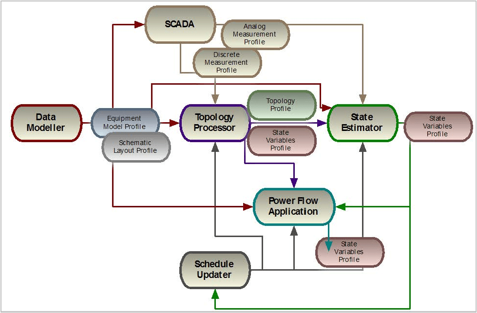
IEC 61970-452 was the original CIM profile (now called a profile group). This is the Common Power System Model (CPSM) which is used for the exchange of electrical power system node-breaker models. Originally developed to define exchanges between EMSs, it has since grown to encompass the exchanges between multiple systems within the transmission environment. The key profiles within this group are Equipment, Short Circuit, and Operation profiles. There are other profiles standardized in different IEC standards that define Topology, State Variables, Diagram Layout profile, etc. Together they all comprise the data exchanges between systems as part of the network analysis process (EMS or other systems) as shown in Figure 6-4.
Each instance of a profile (that is, when the profile is implemented and data is generated) is known as a dataset and there are often dependencies between each dataset allowing it to reference objects that exist in another dataset. For example:
- The
Equipmentdataset contains only internal references and so is not dependent on any other datasets. - The
Topologydataset is dependent on theEquipmentdataset as it has references into objects that are created inEquipment. - The
State Variablesdataset (or datasets) are dependent on bothEquipmentand/orTopologydatasets as it may contain references to pieces of equipment and theirTerminalobjects and/orTopologicalNodeobjects that are in theEquipmentandTopologydatasets. - The
Diagram Layoutdataset will reference the equipment and may also have references toTopologydata. - The
Measurementdatasets will reference the data in theEquipmentdataset.
Common Distribution Power System Model
The Common Distribution Power System Model (CDPSM) is the distribution equivalent of CPSM, building on the standard balanced network model with additional data used to model low-voltage distribution networks. The primary additions are:
- Classes to define the individual phase components for unbalanced network
- Asset information to tie the functional electrical model to the physical assets
- Catalogues of equipment parameters that are defined once then shared across multiple instances
- Geographical data to define the physical location of assets and/or functional components
Since distribution networks can specify the electrical properties of their equipment either explicitly for each instance (as is the case with the CPSM) or as catalogues, the Equipment profile from the CPSM is split into a core Functional profile that defines the basic electrical connectivity, voltages, and so on. This is combined with either the Asset profile which specifies catalogues of equipment properties or an Electrical Properties profile that adds the explicit properties to each instance.
The Topology and State Variables profiles from the CPSM are re-used, unaltered and the Geographical profile adds the geographical location data. Future versions of the CDPSM will also use the Diagram Layout profile and may also use the Measurement profiles.
The core CDPSM profile group therefore becomes:
- Functional
- Electrical Properties
- Asset
- Geographical
- Topology
- State Variables
The re-use of Topology and State Variables from the CPSM is an example of how modular profiles are used in different groups that cover similar areas even when the standards are developed by different working groups . The Geographical profile is also a generic profile that is not tied to a distribution representation. It associates to assets or functional components and with a loose association at the high level it can be used with high-voltage transmission systems as well as the low-voltage distribution network.
The target is to merge into a single family of profiles that will be used for both transmission and distribution.
ENTSO-E
The European Network of Transmission Systems Operators for Electricity (ENTSO-E) started an initiative in November 2007 to move from their existing UCTE Data Exchange Format (DEF) for load flow and three phase short circuit studies, a white space delimited ASCII file format, to a CIM XML based exchange. At that time, ENTSO-E exchanges involved high-voltage bus-branch planning models rather than the node-breaker models that the CPSM was developed for.
The CIM for Planning work was influenced by ENTSO-E’s requirements and ENTSO-E also joined the CIM for Dynamics project to define a standard for exchanging dynamic models. ENTSO-E wanted to use standards wherever possible and since the project’s inception the ENTSO-E profile has converged with that of the CPSM, using the Topology profile for the Buses in the system along with the Equipment and State Variable profiles. In 2016 an interoperability test was held for CGMES Version 2.4. This profile group included:
Equipmentprofile from IEC 61970-452Topologyprofile from IEC 61970-456State Variablesprofile from IEC 61970-456DiagramLayout profile from IEC 61970-453Dynamicsprofile from IEC 61970-457Geographicalprofile from IEC 61968-13
The ENTSO-E exchange specification was thus a profile group containing profiles from a number of IEC standards. All the profiles derive from the same CIM UML (in this case, CIM v16) and by modularizing the profiles and data in this way, applications need to access and import only the data required for their own internal processes. Later in 2017, ENTSO-E specification was transformed in IEC technical specifications, namely IEC TS 61970-600-1:2017 and IEC TS 61970-600-2:2017.
Following the requirements in the European Network Codes and the need to resolve issues in CIM16, in 2021 CGMES v3.0 was released as IEC standard – IEC 61970-600-1:2021 and IEC 61970-600-2:2021 and IEC technical specifications related to CGMES v2.4 were withdrawn. Nevertheless some processes are still using CGMES v2.4 but planning to transition to upper versions in order to satisfy business needs and improve on interoperability when exchanging detailed power system models.
Footnotes
25 “Energy management system application program interface (EMS-API) – 61970 Part 452: CIM static transmission network model profiles”, IEC, Edition 3, 2016.
26 “Application integration at electric utilities - System interfaces for distribution management – 61968 Part 13: CIM RDF Model exchange format for distribution”, IEC, Edition 1.0, June 2010.
27 “Energy management system application program interface (EMS-API) – Part 600-1: Common Grid Model Exchange Specification (CGMES) – Structure and rules”, IEC 61970-600-1, Edition 1, 2021 and “Energy management system application program interface (EMS-API) – Part 600-2: Common Grid Model Exchange Specification (CGMES) – Exchange profiles specification”, IEC 61970-600-2, Edition 1, 2021
28 CPSM is developed and maintained by IEC TC57 Working Group 13 while the CDPSM is from Working Group 14.
29 The project began under UCTE, the Union for the Coordination of the Transmission of Electricity which then became ENTSO-E in July 2009.
Case Study
With so many classes, attributes, and associations, when Jeff Kimble attended the CIM University training he was soon overwhelmed by the amount of information. It was difficult to even know where to start. Further, it turns out that the CIM isn’t a single standards document, but “families” of documents apply to each of the standards that make up the CIM (IEC 61970, 61968, 62325). The power of the CIM is its reuse of definitions and the mapping of relationships between all of the entities, but the double-edged sword of this is that it can be difficult to understand where to begin.
Jeff did learn however that the CIM is maintained in a tool called “Enterprise Architect” (available from Sparx Systems). It uses standard UML to diagram the classes, associations, and attributes. He found that the three standards that make up the CIM (61968, 61970, and 62325) are organized in three high level packages – a convenient way to begin his CIM journey. He learned that by simply using the search function (Ctrl-F within the tool) he can search on a topic of interest whether that is an asset like a transformer or a more abstract concept like a customer. Once he finds a topic of interest he can learn more about its relationship with other concepts be finding where the topic (class) exists in the various diagrams. Very soon he becomes comfortable with navigating around the tool and learning how to find the information that he is interested in. Further, since the tool can export and import UML, he learns that the UML can be exported to any other tool that is UML compliant.
In the CIM, the lowest level model (syntactic) is the:
A
Information model
B
Informative model
C
Implementation model
D
Contextual model
D. Contextual model
A CIM profile is:
A
A subset of the model that may be more restrictive in its definition
B
A subset of the model that is less restrictive in its definition
C
A view of the model from the side
D
A contextual view of the model
A. A subset of the model that may be more restrictive in its definition
The Interface Reference Model (IRM) shows:
A
All of the interfaces supported by the CIM
B
The references used to develop the CIM
C
A description of how to interface from two different systems
D
A logical grouping and scoping of IEC 61968/IEC 61970 interfaces
D. A logical grouping and scoping of IEC 61968/IEC 61970 interfaces
The Common Distribution Power System Model (CDPSM) is the:
A
Standard for defining balanced power systems
B
Extends the standard for balanced power systems to model low voltage distribution systems
C
Model that defines the EMS
D
Model that defines ENTSO-E
B. Extends the standard for balanced power systems to model low voltage distribution systems
Each instance of a profile is known as a:
A
Dataset
B
Model
C
Profile
D
Logical grouping
A. Dataset


