Learning Objectives
- Understand how to map application interfaces using the CIM
- Understand how to create a XSD-based profile from the CIM using CIMTool
Mapping Application Interfaces to CIM
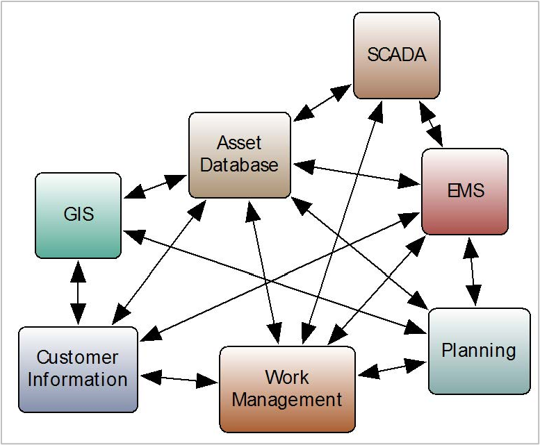
As well as exchanging full power system model data as CIM RDF XML, the other main application of the CIM is as a common semantic model for enterprise application integration. Within utilities there are an increasing number of applications that must communicate with each other. At most utilities, this often results in a large number of point-to-point interfaces using custom formats and protocols to exchange data between software applications from a diverse collection of vendors. Adding a new application to the system requires additional interfaces to be defined and implemented, further increasing the complexity of the overall system.
This results in an application ecosystem that is often referred to as “brittle”. This is because a change to one system’s interfaces may break the interfaces with another system. Additionally, the Total Cost of Ownership (TCO) of such a system is higher as each system has its own data definitions that must be mapped and managed for every interface to another system.
As illustrated in Figure 8-1, even for a small section of the overall enterprise system, this can result in a large number of inter-application communication links. As companies expand their ICT (Information Communication Technology) infrastructure or replace existing applications with products from other vendors they must define new interfaces for each communication link, a process that is time consuming and expensive.
Enterprise Service Bus
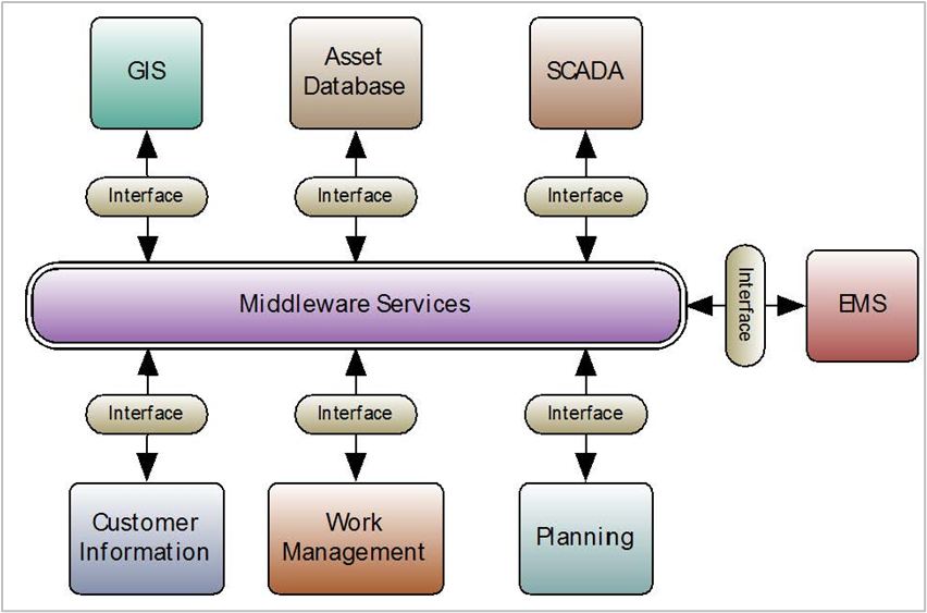
As shown in Figure 8-2, middleware services replace these dedicated links with a single enterprise service bus (ESB). Using middleware services, this provides a mechanism for applications to communicate using a pre-defined message format and requires only a single interface to be written for each application.
For utilities, the CIM provides the common semantic model that can be used to construct messages for communication between the applications.38 This requires each application to map its external interface to the CIM class structure allowing the inter-application messages to be defined in the CIM.
These messages, in XML format, use a restricted CIM XML Schema to define the payloads of the messages. This takes the standard CIM Schema, itself created from the CIM UML class structure and restricts the multiplicity of associations and required attributes and introduces a strict message hierarchy. Again, this is where the profile concept it useful; the profile is a subset of the model that is typically more restrictive, to facilitate application interoperability.
Footnotes
38 For further information, see “The Root of All Data Exchange – Common Information Model,” IEEE Power & Energy Magazine, Volume 14, Number 1, January/February 2016 (the entire issue is dedicated to CIM).
Mapping CIM Profiles to XML Schema
The IEC has issued the 62361-100 standard for CIM profiles to XML schema mapping39 to ensure effective and consistent mapping of the CIM UML into XML Schema messages. These standards follow the United Nations/Center for Trade Facilitation and E-Business (UN/CEFACT) rules for deriving profiles from an information model.
In essence the 62361-100 standard defines how a UML element can be mapped into XML Schema, how references are defined (containment or by reference), when an attribute becomes a child element or XML attribute, and so on. This removes ambiguity for deriving schema and ensures multiple users and vendors will produce compatible schema. This international standard was issued in 2016 and the reader is urged to refer to the IEC document for more explicit details on how the CIM UML maps to XML Schema.
A number of free, open-source and commercial tools are available to automate the mapping of CIM profiles to XML. CIM tools most often mentioned in responses to a CIM survey in 2016 included the following:
- CIMTool by CIMUG (formerly Langdale Consultants)
- CIMSpy and CIMdesk by Power Info LLC
- CIMConteXtor by Zamiren
- Affirma, formerly CIM EA by Xtensible Solutions
- Cimphony by Open Grid Systems
- MODSARUS by EDF R&D
More information on these tools is provided later; but for purposes of illustration, CIMTool will be used here to provide an example of how to derive an XSD.
Footnotes
39 IEC 62361-100: Power systems management and associated information exchange – Interoperability in the long term – Part 100: CIM profiles to XML schema mapping.
Existing Application Data
As a simple example, an EMS application’s external interface may provide the user with access to data on transformers within the system. The EMS application’s interface attributes for a transformer are:
- TRANS_NAME – The Transformer’s name
- WINDINGA_R – The Transformer’s primary winding resistance
- WINDINGA_X – The Transformer’s primary winding reactance
- WINDINGB_R – The Transformer’s secondary winding resistance
- WINDINGB_X – The Transformer’s secondary winding reactance
- WINDINGA_V – The Transformer’s primary winding voltage
- WINDINGB_V – The Transformer’s secondary winding voltage
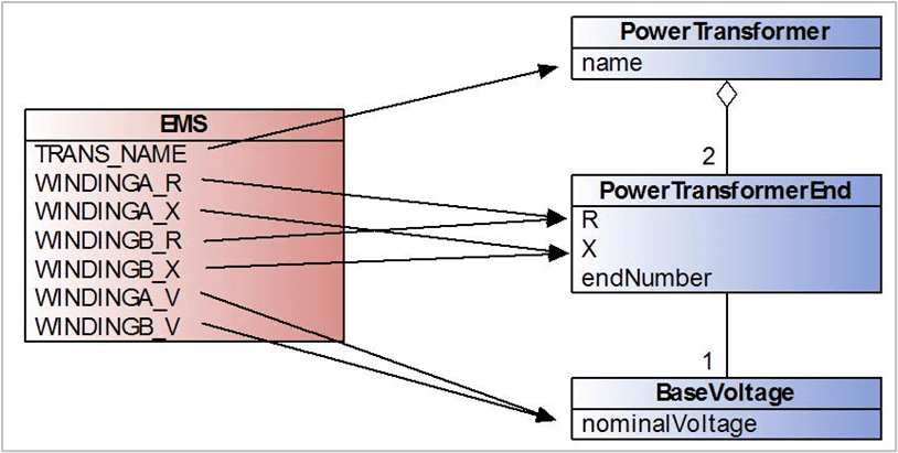
Each of these attributes can be mapped to a corresponding attribute within a CIM class, resulting in an interface to CIM mapping.
This mapping, shown in Figure 8-3, highlights that although the two windings have separate names in the interface, they map to the same attributes within the CIM class structure. The aggregation relationship between the PowerTransformer and PowerTranformerEnd class has, however, been changed from a 0..n multiplicity to 2 (since in this example the EMS represents all transformers as having two windings). This means that there must be two instances of the PowerTransformerEnd class present in the message, with the endNumber attribute then used to differentiate between the primary and secondary windings.
The voltage for each winding is contained with the nominalVoltage attribute of the BaseVoltage class. The BaseVoltage instance is associated with the PowerTransformerEnd directly. The multiplicity is thus 1 on the PowerTransformerEnd-BaseVoltage association.
This small CIM message can now be converted into an XML Schema and used to define the interface.
XSD Definition in CIMTool
Defining the Message Structure
CIMTool is an open source40 tool that supports the definition of CIM profiles and the resulting XML Schema and RDF Schema artifacts. It is available as a standalone application and as an Eclipse plug-in. For this example CIMTool v1.9.3 is used with CIM v15.
Once a CIMTool Project has been created using the CIM15 schema a new profile can be created that will define the subset of the CIM that will be used in the Transformer Data interface.
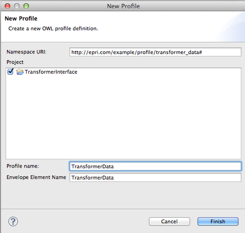
In Figure 8-4 is an example of a New Profile dialog box. Each profile has a namespace Unique Resource Identifier which in this case we have set as http://epri.com/example/profile/transformer_data#. The Profile Name is used to name the profile within the workspace and the Envelope Element Name defines the root of the message itself.
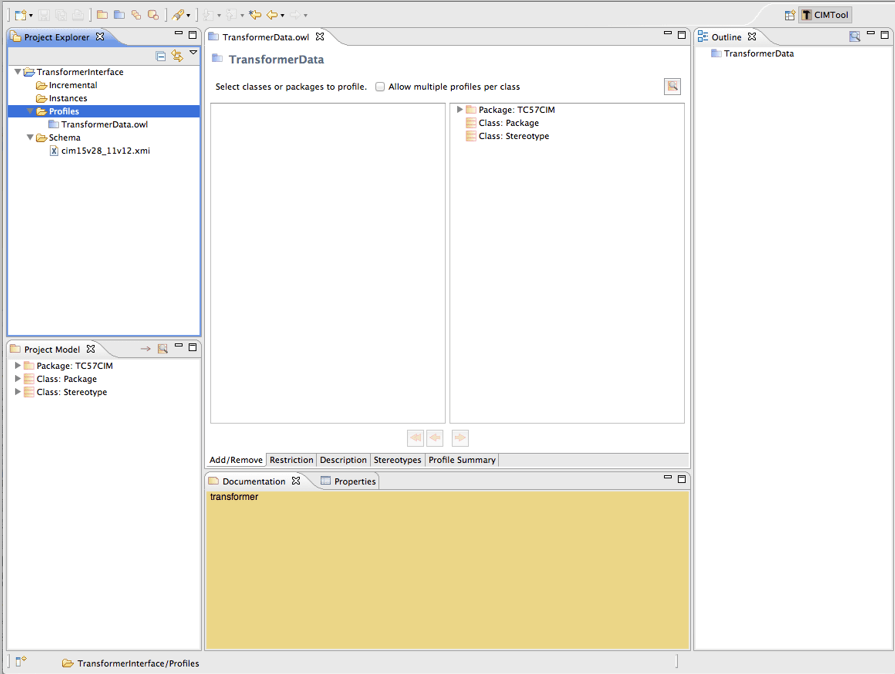
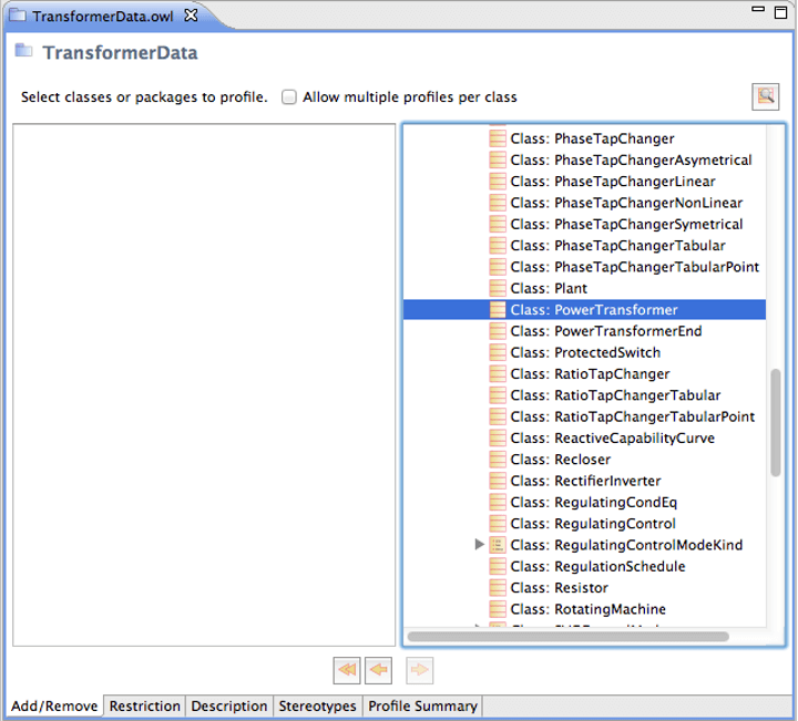
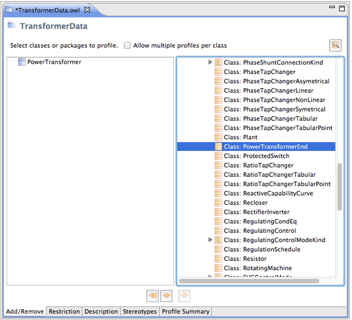
This produces an empty profile called TransformerData as shown in Figure 8-5, which can be populated with classes taken from the full CIM UML model. To do this the CIM package hierarchy is expanded within the Add/Remove window’s right-hand column and the class to be added (in this case PowerTransformer is located). Alternatively, CIMTool’s search functionality can be used to search for the class by name.
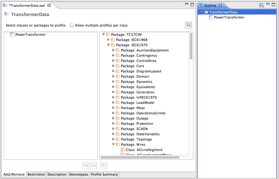
When the class is located it can be added by clicking the left arrow icon at the bottom of the window. This adds the class to the message as shown in Figure 8-7 below.
The Outline view is now updated showing the single class within the message below the root TransformerData element. At this stage however the PowerTransformer is an abstract class so it must be marked as concrete.
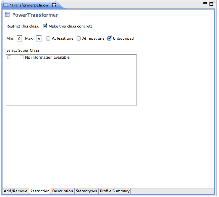
As shown in Figure 8-8, this is accomplished by selecting the Make this class concrete option in the Restriction options page for the PowerTransformer class. Child classes can now be added for PowerTransformer which means that the PowerTransformerEnd association is to be included in PowerTransformer and then include the PowerTransformerEnd class itself in the message. These two steps are shown in Figure 8-9 and Figure 8-10 below.
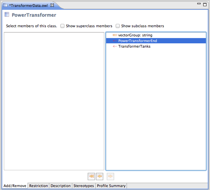
The PowerTransformerEnd association on the PowerTransformer class must now be told to use the PowerTransformerEnd class that has been added. This can be accomplished by selecting the PowerTransformerEnd association and marking the Associated Class to be the PowerTransformerEnd. This is done via the Restriction option page as shown below in Figure 8-11.
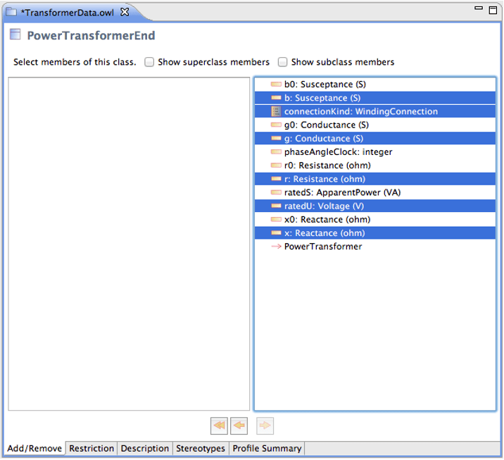
The PowerTransformerEnd class itself has attributes and so the native attributes are selected that are to be added, in this the r and x for the resistance and reactance, and some additional attributes for will also be added for susceptance, conductance, the winding connection type and rated voltage.
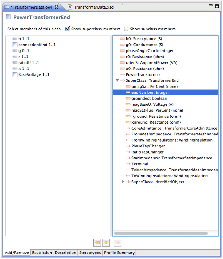
In addition to these native attributes the profile requires the endNumber attribute that is within the PowerTransformerEnd’s superclass, TransformerEnd. To add this the Show superclass members option is selected and then add in the endNumber attribute as shown in Figure 8-13.
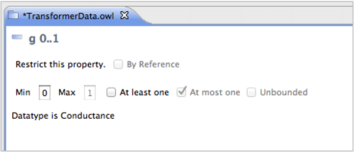
Not all of the attributes that have been added are mandatory, so some attributes such as the conductance may be marked as being optional by changing their cardinality from 1..1 to 0..1 by deselecting the At least one option as shown in Figure 8-14. This allows all attributes for the r and x in the PowerTransformerEnd class to be marked optional.
As well as the PowerTranformer and PowerTransformer class, the last class required is the BaseVoltage. This is added using the same process as the PowerTransformer and PowerTransformerEnd, locating it within the CIM UML and adding it to the message. For the BaseVoltage the only attribute required is the nominalVoltage which is marked as mandatory.
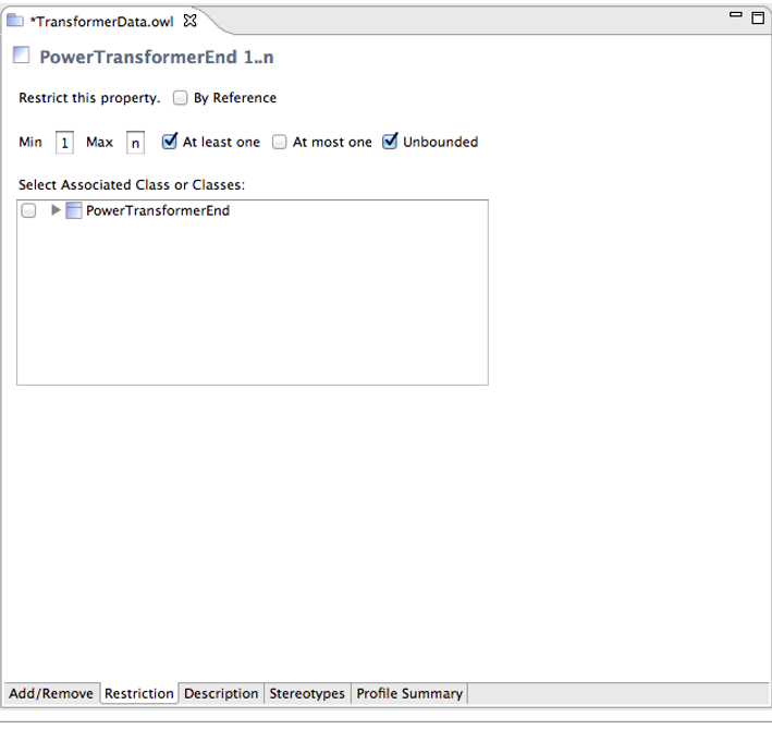
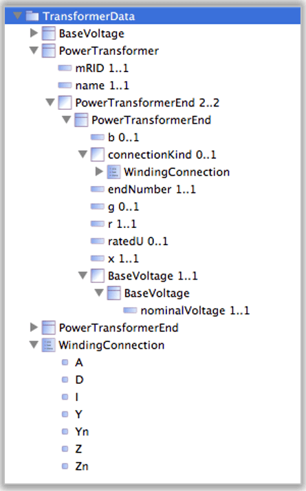
In addition, to complete the message also add the name and mRID attributes to PowerTransformer which are inherited from its IdentifiedObject parent class and the cardinality on the PowerTransformerEnd association is changed from 1..n to 2..2, thus restricting it to having exactly two child entries. The WindingConnection enumeration is included to allow the type of winding connection (Delta, Wye, and so on) to be specified. The resulting message outline is shown in Figure 8-15 below.
Generating XML Schema
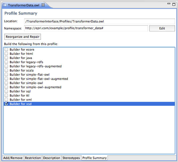
Now the profile has been defined and the message structure has been defined, CIMTool will generate the required artifacts. As an XML Schema is desired, the XSD builder is enabled in the profile options as shown in Figure 8-16, which will create an XSD for the defined message.
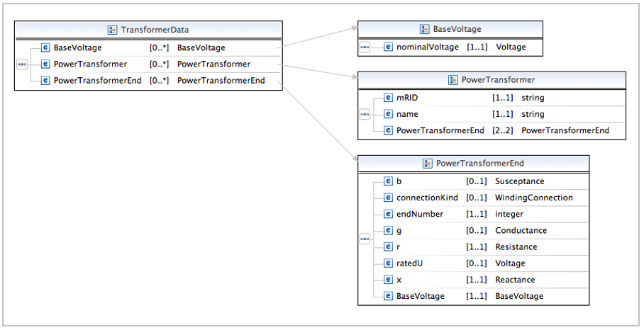
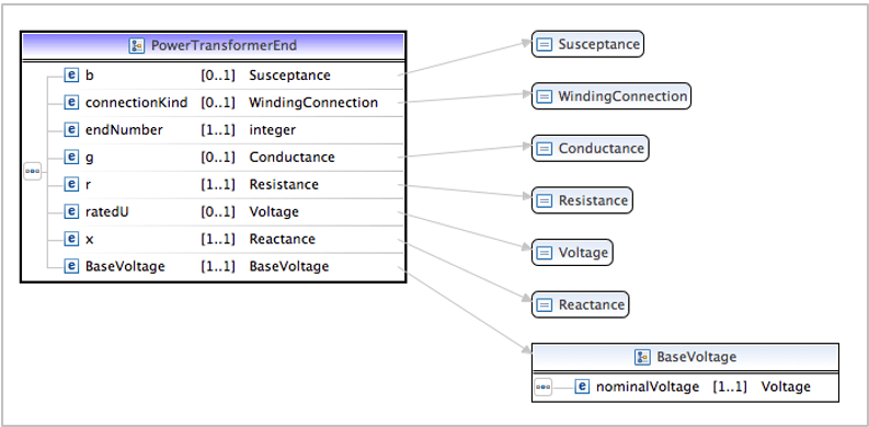
The generated XSD can be viewed both in its raw XML form or using the Eclipse XML Schema viewer. The resulting XSD when viewed in the schema viewer is shown in Figures 8-17 and 8-20 below:
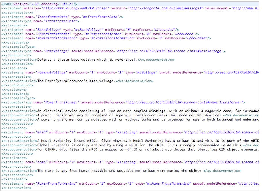
The XML Schema itself is also viewable as shown in Figure 8-21. This conforms to the XML Schema standard and includes the documentation from the UML that is pulled through into the XML Schema documentation itself, allowing complete traceability from the CIM UML to the XML Schema.
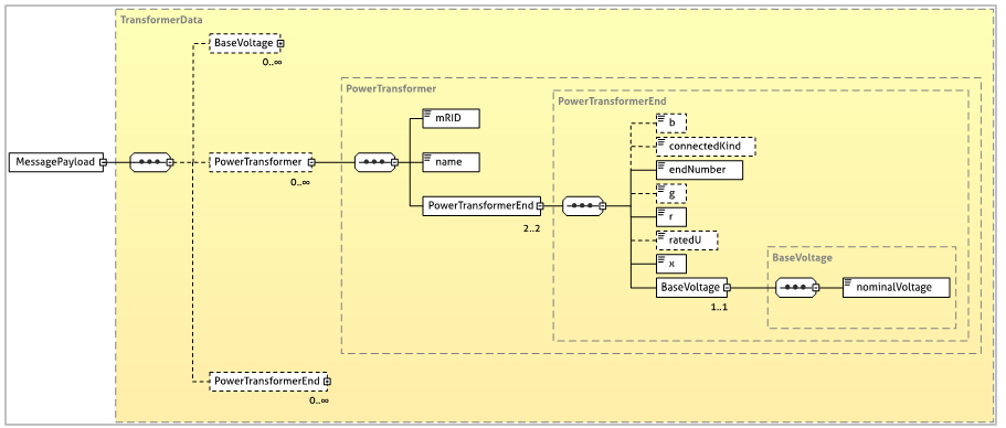
The schema can be used by a number of applications, frameworks and tools. Users familiar with XMLSpy can view the XSD in a view similar to that shown in Figure 8-22 below.
XML Instance Data
This schema now defines the structure of the data for this small, simple interface. This can be used to define the contents of a service contract (that is, Web Service Description Language – WSDL) so that the sending and receiving systems know the format and structure of the data that is to be exchanged.
Using the schema defined above, the resulting XML instance data would take the form shown below:
<?xml version="1.0" encoding="UTF-8"?>
<cim:TransformerData
    xmlns:cim="http://epri.com/example/profile/transformer_data#">
  <cim:PowerTransformer>
       <cim:name>Open Grid Transformer</cim:name>
       <cim:mRID>_836f6720-fde1-11e0-a6f7-e80688cf8a29</cim:mRID>
       <cim:PowerTransformerEnd>
           <cim:b>0.02</cim:b>
           <cim:connectionKind>D</cim:connectionKind>
           <cim:r>0.23</cim:r>
           <cim:ratedU>420.0</cim:ratedU>
           <cim:x>0.78</cim:x>
           <cim:BaseVoltage>
              <cim:nominalVoltage>400.0 </cim:nominalVoltage>
           </cim:BaseVoltage>
       </cim:PowerTransformerEnd>
       <cim:PowerTransformerEnd>
           <cim:b>0.03</cim:b>
           <cim:connectionKind>D</cim:connectionKind>
           <cim:r>0.46</cim:r>
           <cim:ratedU>290.0</cim:ratedU>
           <cim:x>0.87</cim:x>
           <cim:BaseVoltage>
              <cim:nominalVoltage>275.0</cim:nominalVoltage>
           </cim:BaseVoltage>
       </cim:PowerTransformerEnd>
    </cim:PowerTransformer>
</cim:TransformerData>
The namespace is identical to that of the namespace defined for the original profile and while the structure is similar to that of the CIM RDF XML examples, the most noticeable difference is that the data is hierarchical in nature. For this example only the PowerTransformer was given a unique identifier in the form of its mRID attribute (in this case a UUID) but the same attribute could have been added to the PowerTransformerEnd should there be a need to identify them via their mRID.
For the scope of the message, this means that the PowerTransformer element contains the entire required data making it simpler to then transform the element into another format if that is required. These messages are aimed at smaller, message-based exchanges rather than the large, bulk data exchange using CIM RDF XML.
XML Messaging Summary
This example has shown how a simple portion of an application’s interface can be mapped to the CIM class structure and then used to construct a simple XML message payload using CIMTool. Real-world examples often use tens or even hundreds of elements to construct a message payload. The benefit of this approach is that when every application within the system is mapped to this common model it becomes far simpler to enable applications to communicate. The CIM provides a common semantic model, which provides consensus on the interpretation of each class and attribute, removing ambiguity and duplication of definitions.
Footnotes
40 Licensed under the GNU Lesser General Public License v2.1.
Case Study
Jeff Kimble has learned that the CIM model can also be restricted via a profile for enterprise application integration. This is helpful because when he first started it seemed like the CIM had to be used in its entirety which would seem to be unwieldy. It turns out that the CIM is a reference model, much like a dictionary is used to lookup words, and the CIM can therefore be used to look up standard meanings and relationships among the classes.
This ability to use the CIM as a reference model has considerable appeal to Jeff. As the head of the integration team he has seen numerous naming conventions for the services and adapters that have both been provided by vendors or developed by his own team or when his company has worked with systems integrators. The amount of time it takes for someone to get up to speed on all the variations is tremendous. Jeff realizes that if they use the CIM as a reference model, as new adapters are adding to the enterprise service bus, this will cut down on the amount of mapping that is required from one interface to another, drastically lowering the maintenance costs. Further, instead of using disparate definitions for meanings on attributes, his team, and the other teams that they work on the behalf of, will all have a single place to go to reference these meanings. In short, the organization will use a common vocabulary which will have a positive impact on requirements gathering when new interfaces are designed.
System interfaces are referred to as 'brittle' when:
A
There are consistent standards for how interfaces are designed
B
There are many interfaces; inconsistently applied, where a change in one could impact a change in another
C
The interface is made with a less flexible material
D
The interfaces have been harmonized to eliminate duplication
B. There are many interfaces; inconsistently applied, where a change in one could impact a change in another
An example of an artifact in the way the CIM refers to it is:
A
An XSD that can be used for messaging
B
A file that is used by archeologists
C
A file that is leftover by the profile definition process
D
A profile
A. An XSD that can be used for messaging
The specification that guides how the CIM UML is mapped into XML Schema messages is:
A
IEC specification 62361-100
B
The schema specification
C
The CIM
D
XML
A. IEC specification 62361-100
One way that traceability is supported in the creation of profiles is that:
A
A GPS locator is attached to the file
B
Documentation from the CIM is passed to the documentation tag of the resulting XML
C
A master resource identifier (mRID) is used
D
A line is created in the resulting file that points to the source
B. Documentation from the CIM is passed to the documentation tag of the resulting XML
A benefit of using a common reference model for developing is that:
A
The interfaces are more expensive to maintain
B
The developer has to look up an attribute every time that it is used
C
It is common, so everyone understands it
D
It reduces ambiguity, the amount of mapping that needs to be done, and removes the duplication of definition
D. It reduces ambiguity, the amount of mapping that needs to be done, and removes the duplication of definition
